Edwards Signaling Data Sheet E-FSA64 Analog Addressable Life Safety System
Open the original PDF document
View PDF

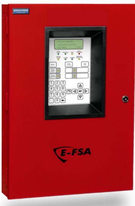
64-Point Analog/Addressable Life Safety System E-FSA64


APPROVAL #6020
Overview
The Edwards Signaling E-FSA64 life safety system offers the reliability of analog/addressable fire detection for small to mid-sized applications. Built to provide years of trouble-free service, this system benefits building owners and installers with rotory device addressing, optional Ethernet® connectivity, and a full line of easilyto-configure option cards and modules.
The E-FSA64 provides one Class B analog/addressable device loop that supports up to 64 device addresses, and two Class B Notification Appliance Circuits (NACs). Optional Class A device wiring is available with the use of a module.
The E-FSA64 supports a wide range of accessories and related equipment, including:
- Intelligent modules and pull stations
- Intelligent detectors, and bases
- Remote annunciators
- Option cards that expand system capacity and extend system capabilities.
Features
- Comes standard with one loop that supports up to 64 analog/ addressable devices of any type and two Class B NACs
- Form C contacts for alarm and trouble, Form A for supervisory
- Rotory addressing
- Optional Ethernet port for diagnostics, programming and a variety of system reports
- Two programmable switches with LEDs and custom labeling
- Supports horn silence over two wires and UL 1971-compliant strobe synchronization
- Optional Class A wiring
- Supports up to eight serial annunciators, (LCD, LED-only, and graphic interface).
- Can use existing wiring for most retrofit applications
- Upload/download remotely or locally
- Two-level maintenance alert reporting
- Pre-alarm and alarm verification by point
- Adjustable detector sensitivity
- 4 x 20 character backlit LCD display
- Optional earthquake hardening: seismic Importance Factor 1.5
Application
The E-FSA64 life safety system is a reliable analog/addressable solution for small to mid-sized buildings. Analog/Addressable Technology delivers the benefits of flexible system installation, while a clean and easy-to-operateuser interface makes panel operation and system maintenance quick and intuitive.
Reliability you can count on
The inherent fault-tolerant characteristics of Analog/Addressable Technology boosts the reliability of E-FSA64 systems. When combined with E-Series smoke and heat detectors, this system delivers a level of dependability not previously available for small to mid-sized applications. All E-Series systems are built to exacting Edwards reliability benchmarks and meet ISO 9001 standards for quality, in addition to agency listings for dependability.
Flexibility built right in
Two fully-programmable front panel switch/LED combinations provide an added measure of flexibility. Their slide-in labels take the mystery out of custom applications, and present a clean finished appearance.
Perfect for retrofits
The E-FSA64 is particularly well-suited to retrofit applications. All connections are made over standard wiring – no shielded cable required. This means that in most situations existing wiring can be used to upgrade a legacy control panel to E-FSA64 technology without the expense or disruption of rewiring the entire building.
Signals with a difference
E-FSA64 NACs are configurable to fully support Edwards notification appliances. These devices offer precision synchronization of strobes to UL 1971 standards. Enabling this feature allows connected horns to be silenced while strobes on the same two-wire circuit continue to flash until the panel is reset.
Clear-cut remote annunciation
Remote annunciation is a strong suit of the E-FSA64. Up to eight annunciators can be installed on a single system. Compatible annunciators include a range of LED and LCD models that provide zone or point annunciation, as well as common control capabilities.
The E-FSA64 also supports graphic annunciation with optional RA Graphic Annunciator interface modules. Each interface provides common control, indicators, and 32 LEDS. Consult the Ordering Information section for details.
A complete line of accessories
The E-FSA64 life safety system is supported by a complete line of analog/addressable detectors, modules and related equipment. Consult the Ordering Information section for details.
Operation
00:00:00 01/01/07 The front panel provides an easy-to-use operator's interface, as well as all the necessary controls for front panel programming. A large back-lit 80-character LCD displays system status, event details, and programming prompts. Large tactile control buttons are easy to see in low light conditions, and bright multicolor LEDs offer at-a-glance status indication.
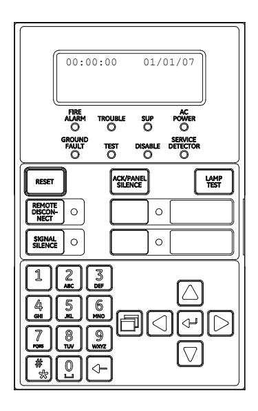
Control buttons
| Button | Description |
|---|---|
| Reset | Initiates a system reset. |
|
ACK/Panel
Silence |
Silences the panel and remote annunciators during
an active trouble, supervisory, or alarm event and acknowledges new event activations. |
| Signal Silence |
Alarm mode: Silences active notification appliances.
Pressing Signal Silence a second time turns NACs back on. |
|
Remote
Disconnect |
Dialer: Disables or enables dialer.
Dialer set to modem only: Disables or enables the common alarm relay. |
| Left arrow |
Display mode: Moves the cursor to the left.
Menu mode: Toggles between programming selections. |
| Right arrow |
Display mode: Moves the cursor to the right.
Menu mode: Retrieves a programming option's sub menu and toggles between a programming option's selections. |
| Up arrow |
Display mode: Advances to the previous event.
Menu mode: Moves the cursor up. |
| Down arrow |
Display mode: Advances to the next event.
Menu mode: Moves the cursor down. |
| Enter |
Display mode: Displays selected event details.
Menu mode: Retrieves a programming option's sub menu or jumps to the Save function in the menu. Entry mode: Enters the selected data into the system. |
| Cancel |
Display mode: Exits the detailed information display.
Menu mode: Exits the current menu level. Entry mode: Clears the current entry. |
| Menu |
Display mode: Enters the menu mode
Menu mode: Exits menu mode |
| Space | Enters a space, such as a space between words. |
|
Alphanumeric
keypad |
Entry mode: Pressing a button once enters the number
on the button. Pressing the button twice enters the secondary value. |
|
Programmable
buttons |
These buttons can be programmed to control or
operate a device, zone, or Panel NAC. The buttons can be labeled with a slip-in insert. |
System LEDs
| LED | Description |
|---|---|
| Fire Alarm |
Red LED. On steady when there is an active
alarm. |
| Trouble |
Yellow LED. Flashes when there is a fault on a
monitored circuit or system component, or when a circuit is disabled. |
| Supv |
Yellow LED. On steady when there is an active
supervisory event. |
| AC Power | Green LED. On when the panel has AC power. |
| Disable |
Yellow LED. Double-flashes when there is a dis
abled circuit, alarm relay, or remote annunciator. |
|
Ground
Fault |
Yellow LED. On steady during an active ground
fault. |
| Test |
Yellow LED. Flashes when performing an audible
walk test. Steady indicates a silent test. |
|
Service
Detector |
Yellow LED. Indicates that detector needs servic
ing. |
| Signal | Yellow LED. On steady indicates that NAC cir |
| Silence | cuits are turned off but the panel is still in alarm. |
| Remote | Yellow LED. On steady indicates that the dialer |
| Disconnect | is disabled or that the alarm relay is enabled or |
| disabled when the dialer is set to modem only. | |
| User keys | Yellow LED. Programmable. |
Panel Operation Options
| Language | English or French |
|---|---|
| Marketplace | U.S. or Canada |
| AC fail delay |
Off: Off-premise notification of an AC power failure
is immediate. 1 to 15 hours: Delays the off-premise notification of an AC power failure by the time period selected. |
| Zone resound |
On: NACs resound each time a device in the zone
goes into alarm even if they were silenced Off: Inhibits the NACs from turning on again (after they were silenced) when a second device in the zone goes into alarm. |
|
Reset inhibit after
NACs turn on |
Off: Panel reset is operational immediately.
1 minute: Panel reset is inhibited for one minute. |
| Auto signal | Off: Allows immediate silencing of signals from an |
| silence |
off-normal condition using the Signal Silence button
5 to 30 minutes: Delays the silencing of signals from an off-normal condition by disabling the Signal Silence button for the time period selected. |
| Day start | Start time for daytime sensitivity |
| Night start | Start time for nighttime sensitivity |
| Date |
U.S.: MM/DD/YYYY
Canada: DD/MM/YYYY |
| LCD banner |
Banner text for line one and line two. Each line is
capable of up to 20 characters. |
| Event notification |
Zone: When a device is a member of a zone, only
the zone information is sent to the LCD display, LEDs, printer, and dialer. Zone/device: Zone information is sent to the LCD display and LEDs. Device information is sent to the printer and dialer. Device: Only device information is reported. |
Programming
E-FSA64 life safety systems are simple to set up, yet also offer programming features that put these small building panels into a class of their own. Auto programming quickly gets the panel operational using factory default settings and basic zone and point settings can be programmed through the front panel interface, so the system is up and running in no time.
E-FSA64 systems also interface to a PC running compatible FSA-CU software. This option offers full system configuration in the familiar Windows® operating environment. Connection is typically made to a laptop through the panel's optional RS-232 communications port, which can also be used to connect a system printer.
The optional network card provides a standard 10/100 Base T Ethernet® network connection that permits access to the control panel from any remote location with the correct communications protocols. The connection can be used to download to the panel from the FSA-CU, or upload and view system reports using the FSA-CU.
Available system reports include:
- Correlation groups Device details
- Device maintenance History
- System status Walk test
- Dialer
-
Internal status System configuration
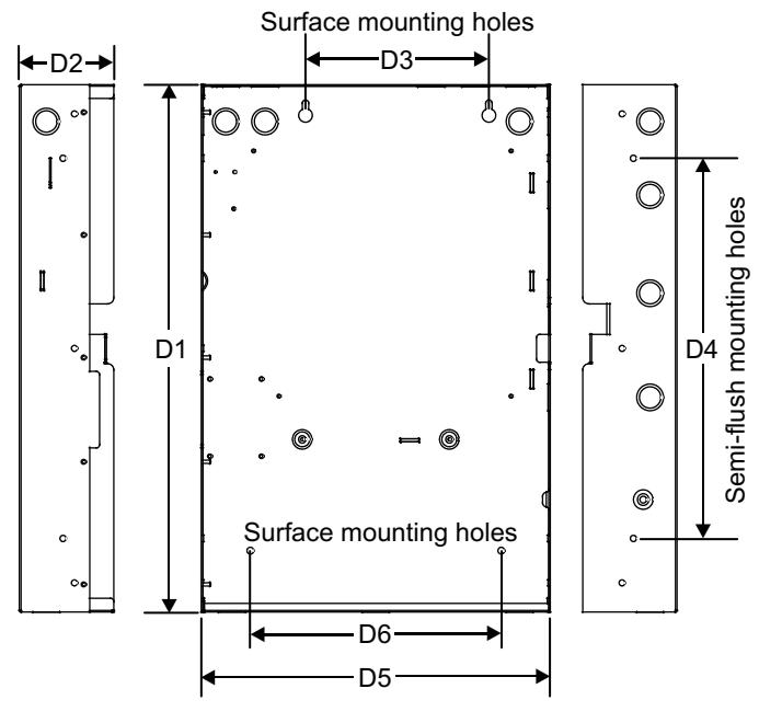
Dimensions
| Panel dimensions, in (cm) | ||||||
|---|---|---|---|---|---|---|
| Model | D1* | D2 | D3 | D4 | D5* | D6 |
| 21.50 | 3.85 | 7.5 | 15.5 | 14.25 | 10.25 | |
| E-FSA64 | (54.6) | (9.8) | (19.0) | (39.4) | (36.2) | (26.0) |
* Add 1-1/2 in. (3.81 cm) to D1 and D5 dimensions for trim kit.
Wiring & Configuration
Notification appliance circuits (TB2)
The E-FSA64 comes equipped with two notification appliance circuits. Each circuit can be individually configured for continuous, temporal, synchronized, and coded output.
| Circuit Spec | Circuit Specifications | |
|---|---|---|
| Circuit Type | 2 Class B, Class A optional when Class A card is | |
| installed. | ||
| Each circuit is 2.5 amps. | ||
| Voltage | 24 VFWR | |
| Current | 3.75 A FWR total at 120/230 VAC 60 Hz | |
| 3.0 A FWR total at 230 VAC 50 Hz | ||
| 2.5 A max per circuit | ||
| Impedance | 26 total, 0.35 μF max | |
| EOLR | 15 K Ω, ½ W | |
Class B wiring
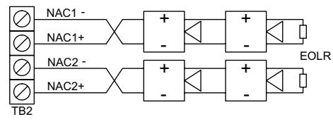
Marking indicates output signal polarity when the circuit is active. Polarity reverses when the circuit is not active. Wire notification appliances accordingly. Notification appliance polarity shown in active state.
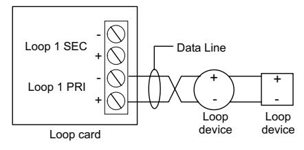
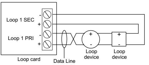
Analog Addressable Device loop
The system provides one device loop circuit that can be used with any mix of analog addressable detectors and modules. The loop circuit is supervised for opens, shorts, and grounds.
| Circuit Specifica | Circuit Specifications | ||
|---|---|---|---|
| Device loops | 1 loop Class B, Class A optional when Class A card is installed. Supporting up to 64 device addresses. | ||
| Communication line voltage | Maximum 20 V peak-to-peak | ||
| Circuit current | 0.5 A max | ||
| Circuit impedance | total, 0.5 μF, max | ||
| Isolators | 64 maximum | ||
Class B wiring
Class A wiring
Alarm, trouble, and supervisory relay (TB3)
The trouble relay is normally-open, held closed, and opens on any trouble event or when the panel is de-energized. The supervisory relay is normally-open, and closes on any supervisory event. The alarm relay changes over on any alarm event.
Relay specifications
| Alarm | Trouble | Supervisory | |
|---|---|---|---|
| Type | Form C | Form A | |
| Voltage | 24 VDC at 1 A resistive | 24 VDC at | 1 A resistive |
Relay circuits can only be connected to power-limited sources.
Auxiliary & Smoke power outputs (TB3)
The control panel provides two auxiliary power outputs which can be used for powering ancillary equipment such as remote annunciators and two wire smoke detectors. Aux 2 can be software selected to operate continuous. The circuit is supervised for shorts and grounds.
Note: For a complete list of devices that can be connected to this circuit, refer to the E-Series Compatibility List 3101063.
| Circuit specifications | ||
|---|---|---|
| Circuit voltage range | 21.9 to 28.3 V | |
| Resettable circuit (Aux power 2) | 24 VDC nominal at 500 mA | |
|
Continuous circuit
(Aux power 1) |
24 VDC nominal at 500 mA. Use this circuit for powering two-wire smoke detectors via E-2WIRE module. | |
Note: Any current above 0.5 amp connected to both Aux 1 and 2 will reduce the total available NAC power by that amount.
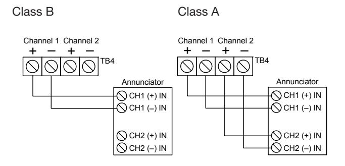
Annunciator loop (TB4)
The control panel provides a connection for up to eight serially driven and supervised remote annunciators.
| Circuit specifications | ||
|---|---|---|
| Device loops | Class B (Style Y) or Class A* (Style Z) | |
| Circuit voltage | 2.55 V | |
| Circuit current | 30 mA max | |
| Circuit impedance | Up to 8 annunciators or 4000 feet, 18AWG wire | |
Option Cards
Edwards Signaling panels are supported by a complete line of modules and related equipment that enhance performance and extend system capabilities. Option cards are easy to install and set up. They simply plug directly into the control panel main circuit board or are connected to it with a ribbon cable. After installation, terminals remain easily accessible for quick connection of field wiring. The cabinet provides ample room for wire routing, keeping wiring neat and easy to service at all times.
SA-CLA Class A Module
The SA-CLA card provides Class A capability for NAC wiring. Its terminal block provides the wiring connection for NAC return wiring. The SA-CLA is compatible with E-FSA64 control panels only. E-FSA250 panels are
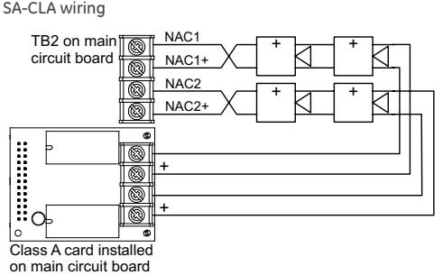
Class A ready. The SA-CLA is installed directly to the control panel circuit board using its plastic standoffs and plug connection.
| SA-CLA specifications | ||
|---|---|---|
| Operating voltage | 24 VFWR | |
| Operating current |
3.75 A FWR total at 120/230 VAC 60 Hz
3.0 A FWR total at 230 VAC 50 Hz 2.5 A max per circuit |
|
| Circuit impedance | 26 ohms, 0.35uF | |
| Terminal rating | 12 to18 AWG (0.75 to 2.5 sq mm) | |
| Operating environment | ||
| Temperature | 32 to 120°F (0 to 49°C) | |
| Humidity |
0 to 93% RH, noncondensing at 90°F
(32°C) |
|
SA-232 RS-232 interface
The SA-232 card provides an RS-232 interface with Edwards Signaling panels. It can be used for connecting a printer to the control panel to print system events. The card also can be used for connecting a computer to download a configuration program from the FSA-CU to the control panel.
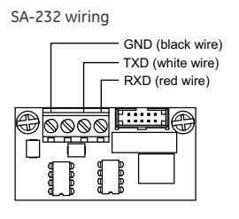
The RS-232 card is installed on the plastic assembly and connects to the main circuit board via a ribbon cable.
| SA-232 specifications | |
|---|---|
| Operating voltage | Standard EIA-232 |
| Terminal rating | 12 to18 AWG (0.75 to 2.5 sq mm) |
| Operating environment | |
| Temperature | 32 to 120°F (0 to 49°C) |
| Humidity | 0 to 93% RH, noncondensing at 90°F (32°C) |
SA-ETH Ethernet Interface Card
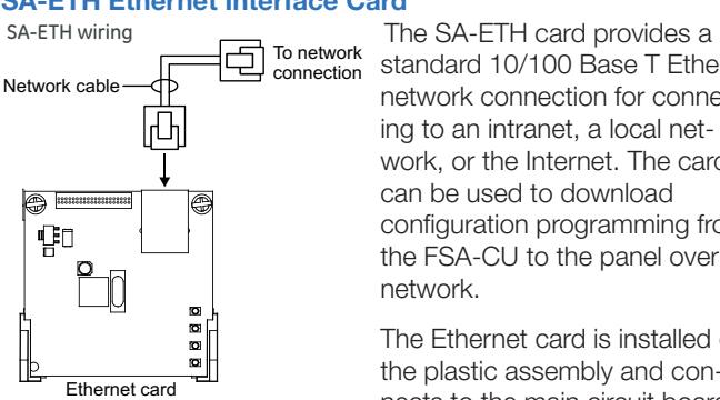
standard 10/100 Base T Ethernet network connection for connecting to an intranet, a local network, or the Internet. The card can be used to download configuration programming from the FSA-CU to the panel over the network.
The Ethernet card is installed on the plastic assembly and connects to the main circuit board via a ribbon cable.
| SA-ETH specifications | ||
|---|---|---|
| Ethernet | 10/100 Base T | |
| Operating environment | ||
| Temperature | 32 to 120°F (0 to 49°C) | |
| Humidity | 0 to 93% RH, noncondensing at 90°F | |
| (32°C) | ||
SA-DACT Dialer
The SA-DACT provides communications between the control panel and the central station over a telephone line system. It transmits system status changes (events) to a compatible digital alarm communicator receiver over the public switched telephone network. The dialer is capable of single, dual, or split reporting of events to two different account and telephone numbers. The modem feature of the SA-DACT can also be used for uploading and downloading panel configuration, history, and current status to a PC running the FSA-CU.
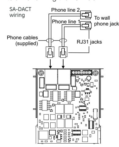
The dialer phone lines connect to connectors on the dialer's main circuit board. Phone line 1 connects to connector J4 and phone line 2 connects to connector J1.
The SA-DACT queues messages and transmits them based on priority (alarm, supervisory, trouble, and monitor). Activations are transmitted before restorations.
The SA-DACT is installed on the plastic assembly and connects to the main circuit board via a ribbon cable.
| SA-DACT specifications | |
|---|---|
| Phone line type | One or two loop-start lines on a public, |
| switched network | |
| Phone line connector | RJ-31/38X (C31/38X) |
| Communication formats | Contact ID (SIA DC-05) |
| Operating environment | |
| Temperature | 32 to 120°F (0 to 49°C) |
| Humidity | 0 to 93% RH, noncondensing at 90°F |
| (32°C) |
| Compatible DACRs | |||
|---|---|---|---|
| Receiver | Models | Formats | |
| Ademco | 685 | Contact ID | |
| FBII | CP220 | Contact ID | |
| Osborne-Hoffman | OH 2000 | Contact ID | |
| Radionics | D6600 | Contact ID | |
| Silent Knight | 9800 | Contact ID | |
| Sur-Gard | SG-MLR1, MLR2 | Contact ID | |
Specifications
| Device loops |
1 loop Class B, Class A optional, supporting
up to 64 device addresses |
|
Notification appliance
circuits |
2 Class B, Class A optional, 2.5 amps each |
| Power supply |
3.75 A FWR total at 120/230 VAC 60 Hz
3.0 A FWR total at 230 VAC 50 Hz 0.5 amps aux power |
| Operating voltage |
24 VDC. NAC minimum voltage: 19.5 VDC
@ 20.4 V battery voltage |
|
Loop circuit operating
voltage |
20 V peak-to-peak |
| Primary power | 120 VAC, 60 Hz, 230 VAC 50-60 Hz |
|
Aux Power 1
(Continuous circuit) |
24 VDC nominal at 500 mA |
|
Aux Power 2
(Resettable circuit) |
24 VDC nominal at 500 mA. |
| Auxiliary output | 19 to 25.7 VDC |
| Base panel current draw | Standby: 155 mA Alarm: 204 mA |
| Battery placement |
E-FSA64 cabinets accommodate up to 10
A/H batteries. Use a external cabinet for larger battery sizes. |
| Batteries |
Batteries must be sealed lead acid type only.
Maximum charging capacity = 26 Ah. |
| Loop circuit |
Maximum loop resistance: 66 Ω. Maximum
loop capacitance: 0.5 µF. Style 4, 6, and 7 |
| wiring. 64 isolators maximum | |
| Compatibility ID | 100 |
| Alarm contact | Form C 24 VDC @ 1 A (resistive load) |
| Trouble contact | Form C 24 VDC @ 1 A (resistive load) |
| Supervisory contact | Form A 24 VDC @ 1 A (resistive load) |
| Environmental | Temperature: 0 to 49°C (32 to 120°F). |
| Humidity: 0 to 93% RH, noncondensing | |
| Terminal rating |
All terminals rated for 12 to 18 AWG (0.75 to
2.5 sq mm) |
| Serial communications | Voltage: 2.55 V. Current: 30 mA max |
| Remote annunciator | 8 drops max, RS-485 Class B, Class A |
| Input zones | 16 max. |
| Agency Listing | UL, CSFM, ULC and NYFD #6020 |
|
E-FSA64 Single Loop Systems
1 Loop System, 64 point capacity, 2 Class B NACs, 2 Line Dialer, Red Door, surface mount enclosure, 115VAC transformer, English. 1 Loop System, 64 point capacity, 2 Class B NACs, Red Door, surface mount enclosure, 115VAC transformer, English. 1 Loop System, 64 point capacity, 2 Class B NACs, 2 Line Dialer, Gray door, surface mount enclosure, 115VAC transformer, English. 1 Loop System, 64 point capacity, 2 Class B NACs, Gray door, surface mount enclosure, 115VAC transformer, English. Flush mount trim, black Dual Line Dialer/Modem, supports Contact ID, mounts in cabinet on base plate. Serial Port (RS-232), for connection to printers & computers, mounts in cabinet to base plate Ethernet Port, Slave, mounts in cabinet on base plate. Class A adapter module. Provides Class A capacity on NACs. Mounts in cabinet on main board. Remote Annunciators (refer to Data Sheet S85005-0128) LCD Remote Annunciators Remote Annunciator, 4X20 LCD & Common Indicators for displaying system status, mounts 4" Square electrical box, red housing. Remote Annunciator, 4X20 LCD, Common Indicators & Common Controls for displaying system status, mounts 4" Square electrical box, red housing. LED Remote Annunciators & Expander Remote Annunciator, Common Indicators for displaying system status, common controls & 16 groups w/2 LEDs each for zone display, mounts to standard 4" Square electrical box, red housing. Remote Annunciator Zone expander, 24 groups of 2 LEDS each for display of alarm and trouble. Each with custom label area. Mounts to standard 4" electrical box, red housing. Graphic Annunciator Drivers Graphic Annunciator Driver, provides outputs for common indicators and 32 alarm/supv zones as well as inputs for common switches. |
|---|
| Provided with a snap track for mounting in custom graphic enclosures. |
| Remote Annunciator Cabinets & Accessories |
| Remote Annunciator Enclosure, key locked with plexiglass window for one RLCD(C) or RLED(C). |
| Remote Annunciator Enclosure, key locked with plexiglass window with space for 2 of either RLCDx, RLEDx or RLED24. |
| Remote Annunciator Enclosure, key locked with plexiglass window with space for 3 of either RLCDx, RLEDx or RLED24. |
| Keyswitch, single gang, provides key operated enable or disable of common controls on RLCD or RLED units. |
| Surface Mount Box - for R-Series Annunciators. |
| Battery Cabinet. 14.0" x 18.25" x 7.25". Holds 2 12V24A batteries. Weight 19lbs (8.6 kg). |
| Battery Cabinet - Red. 14.0" x 18.25" x 7.25". Holds 2 12V24A batteries. Weight 19lbs (8.6 kg). |
|
Seismic hardening Kit for E-FSA series panels. Includes battery hardening for BC-1 enclosure and components to harden panel internal
components. See note below. |
|
Note: For earthquake anchorage, including detailed mounting weights and center of gravity detail, please refer to Seismic Application Guide 3101990-
EN. Approval of panel anchorage to site structure may require local AHJ, structural, or civil engineer review. |
| Standby batteries must be mounted externally from fire panel in separately mounted BC-1 enclosure. Order BC-1 and BC-1EQ separately. |
Continued...
FSA-CU Edwards Signaling FSC/FSA configuration and diagnostics utility.

Contact us...
Phone: 1-800-336-4206
Web: www.edwardssignaling.com
Edwards Signaling is an EDWARDS brand.
3 Farm Glen Boulevard Farmington, CT 06032
In Canada, contact Chubb Edwards... Email: inquiries@chubbedwards.com Web: www.chubbedwards.com
© 2013 UTC Fire & Security Americas Corporation, Inc. All rights reserved. Specifications subject to change without notice. Edwards is part of UTC Climate, Controls & Security, a unit of United Technologies Corporation.
Analog/addressable Devices & Accessories
|
Part
Number |
Description | Ship wt. |
|---|---|---|
| Analog/addressable Detectors & Bases (refer to data sheet S85001-0592) | ||
| E-PHD | Analog/addressable Optical/Fixed Temperature Detector | 0.25 (0.11) |
| E-PDD | Analog/Addressable Duct Detector | 0.25 (0.11) |
| E-PD | Analog/addressable Optical Smoke Detector | 0.25 (0.11) |
| E-HD | Analog/addressable Fixed Temperature Heat Detector | 0.25 (0.11) |
| B4U | Standard Base | 0.11 (0.05) |
| RB4U | Relay Detector Base | 0.11 (0.05) |
| IB4U | Isolator Detector Base | 0.11 (0.05) |
| SB4U | Audible (Sounder) Detector Base | 0.11 (0.05) |
| AB4G-SB | Surface Box for Audible Base | 1.0 (0.45) |
| RLED | Remote alarm LED, use with standard base only | 0.2 (.09) |
|
Modules
E-270 |
Single action pull station | |
| E-278 | Double action pull station | |
| E-IDC1B | One Input Module, mini | |
| E-IDC2B | Two Input Module, double gang | |
| E-IDCWS | Two Input Module, double gang, Waterflow, Supervisory | |
| E-RLY | Analog/addressable relay Module, double gang | |
| E-ISO | Line isolator Module | |
| E-NAC |
Analog/addressable NAC Module, double gang with Edwards strobe
synchronization |
|
| E-IDC1A | One input, class A module, double gang | |
| E-2WIRE | Two-wire Smoke Detector Interface Module, double gang | |
| E-270 | One Stage Fire Alarm Station | |
| E-278 | Double Action Fire Alarm Station | |
| Accessories | ||
| CTM |
City Tie Module. Mounts in 2-gang electric box.
Provides connection to a local energy fire alarm box. |
0.6 (0.3) |
| MFC-A | Multifunction Fire Cabinet, 8" x 14" x 3.5" - RED. | 7.7 (3.5) |
09-06-13