Edwards Signaling CS405 Installation Instructions
Open the original PDF document
View PDFInstallation Instructions for Strobe Signal Appliance
DESCRIPTION
The strobes are high quality notification appliances intended for public mode applications in accordance with the latest edition of NFPA 72, National Fire Alarm Code. It is recommended that these products be installed in accordance with the requirements in the latest edition of national and local fire alarm and electrical codes. The 15/75 cd model and the 110 cd model strobes are suitable for indoor or outdoor applications. For outdoor use, the strobes must be installed with a weatherproof backbox, model 449.
The strobes are self-synchronized to flash at 1 fps across their full operating voltage range. Studies show that people with photosensitive conditions may experience a photoconvulsive response from random flashes of light. This risk is minimized with these strobes. The strobe operates on any existing 2-wire signal circuit. Separately installed "sync control modules" are not required.
Synchronization of less than 200 milliseconds will be maintained for no less than 60 hours supervision followed by 30 minutes in alarm.
See Figures 3 and 4 for product specifications.
INSTALLATION
WARNING: This device will not operate without electrical power. As fires frequently cause power interruptions, discuss further safeguards with your local fire protection specialist.
To reduce the risk of shock, always disconnect all power before handling the unit.
To reduce the risk of shock, do not tamper with unit when circuit is energized. Disconnect all power and allow 5 minutes for stored energy to dissipate before handling.
- For indoor mounting, select a Standard North American 2 gang X 1-1/2" (38 mm) deep electrical box (52151 Series or equivalent). For outdoor mounting, use a weatherproof model 449 backbox. Install the electrical box using suitable hardware.
- 2. Bring signaling circuit field wiring into the electrical box.
CAUTION: Electrical supervision requires wire run to be broken at each device. Do not loop signaling circuit field wires around terminals.
- Connect this unit to a signaling circuit that outputs a constant (not pulsed) voltage. To ensure proper unit function, polarity must be observed. Refer to Figure 2 for wiring connections. For additional wiring connection details, see the installation instructions supplied with the control panel.
-
When connections are complete, mount the unit onto the electrical box as follows:
- a. For indoor mounting, secure the unit using two Phillip head screws (supplied). Complete the enclosure by installing two hole plugs (Part Number P-038845-0019 (supplied)) into the two unused holes in the back plate.
- b. For outdoor mounting, secure the unit using the four Phillip head screws (supplied). Discard the two plastic caps (supplied).
- 5. Apply power and activate the unit to verify that it is operating properly.
MAINTENANCE
CAUTION: Should the unit fail to operate properly, do not attempt repair. Contact the supplier for replacement.
Perform a visual inspection and an operational test twice a year or as directed by the local authority having jurisdiction.
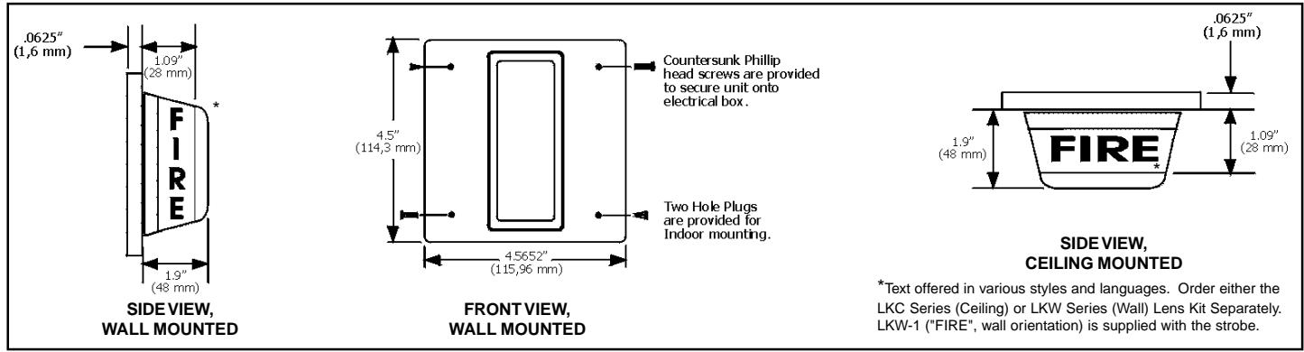
Figure 1. Detailed View
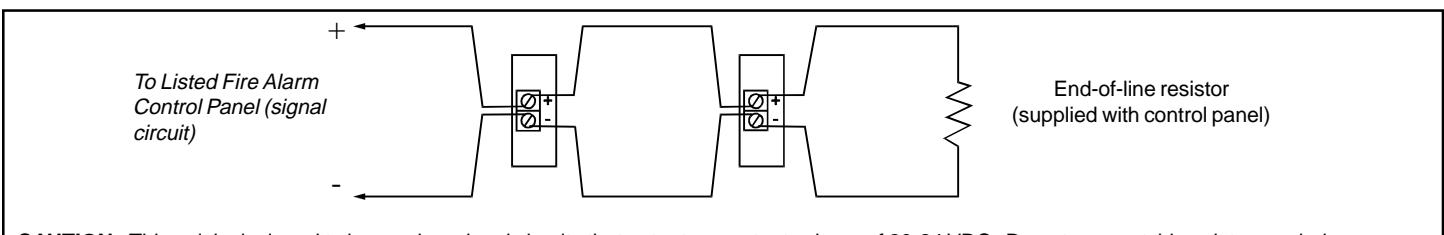
CAUTION: This unit is designed to be used on signal circuits that output a constant voltage of 20-24 VDC. Do not connect this unit to a coded or pulsating voltage. Electrical supervision requires wire run to be broken at each terminal. Do not loop signaling circuit field wires around strobe terminals.
Figure 2. Connecting Strobe Units with Terminal Blocks
SPECIFICATIONS
Operating voltage: 20-24 Vdc Operating current: See figure 3
Flash rate (per second) 1 fps (synchronized)
Light output (cd)
UL 1971 -7A: 15 cd wall UL 1971 - 8A: 110 cd wall
15 cd ceiling 60 cd ceiling
UL 1638 - 7A: 75 cd UL 1638 - 8A: 120 cd
Operating environment
Indoor 85% relative humidity @ 86 °F (30 °C), 32 °F to 120 °F
(0 °C to 49 °C) variable ambient temperature
Outdoor 93% relative humidity @ 86 °F (30 °C), -40 °F to 151 °F
(-40 °C to 66 °C) variable ambient temperature (with
weatherproof box)
NOTE: The 8A strobe may be used in sleeping areas. When used in sleeping areas, the strobe must be wall mounted not less than 24 in. (601 mm) from ceiling and no more than 16 feet (4.88 m) from the pillow. Distance to the ceiling is measured from top of signal lens.
NOTE: This equipment has been tested and found to comply with the limits for a Class A digital device, pursuant to Part 15 of the FCC Rules. These limits are designed to provide reasonable protection against harmful interference when the equipment is operated in a commercial environment. This equipment generates, uses and can radiate radio frequency energy and, if not installed and used in accordance with the instruction manual, may cause harmful interference to radio communications. Operation of this equipment in a residential area is likely to cause harmful interference in which case the user will be required to correct the interference at his own expense.
CAUTION: Changes or modifications to this equipment not expressly approved by the party responsible for compliance could void the user's authority to operate the equipment.
Electronic strobes
CS405-7A-T Electronic strobe, 15/75 cd red CS405-8A-T Electronic strobe, 110 cd red
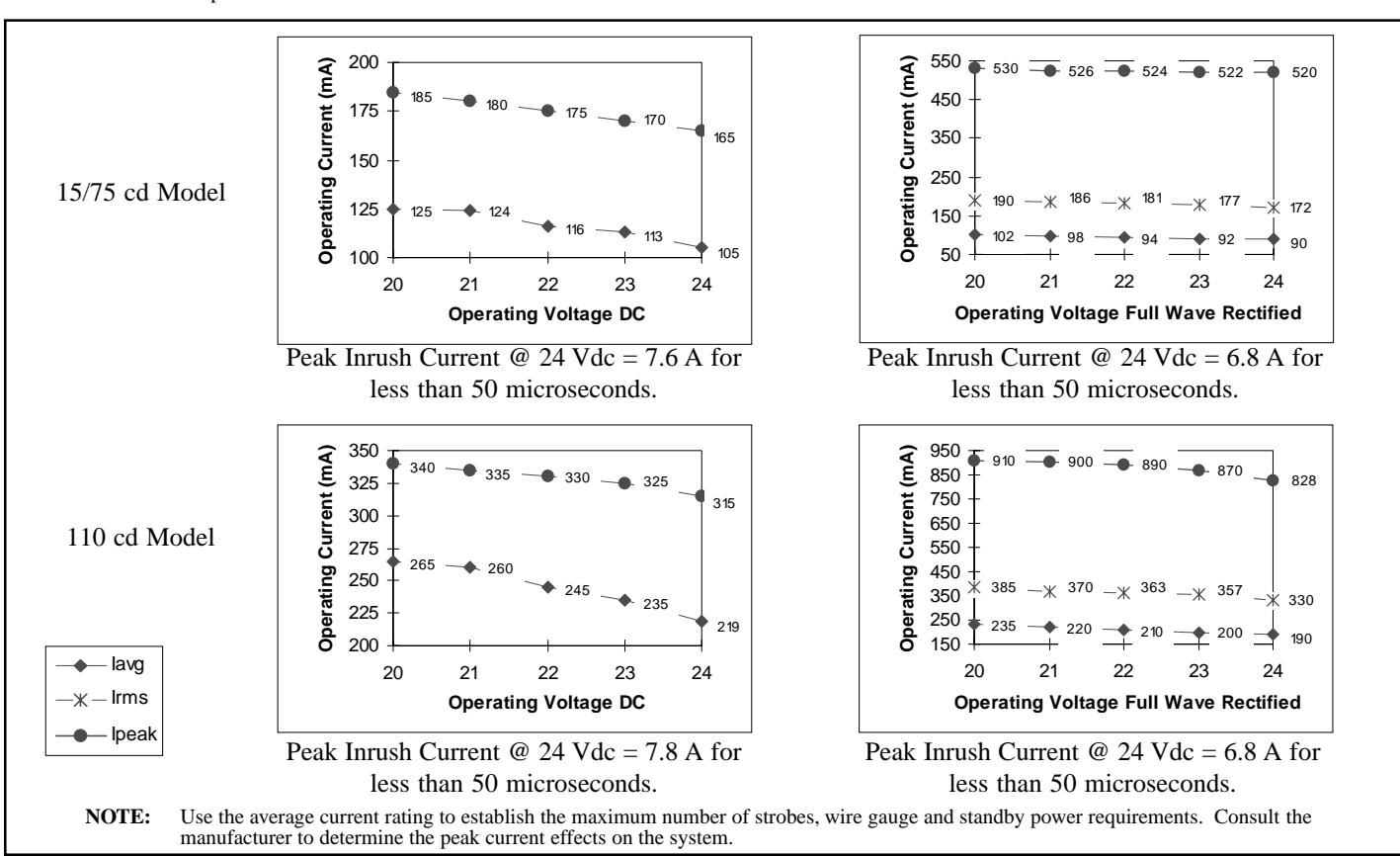
Figure 3. V/I Curves
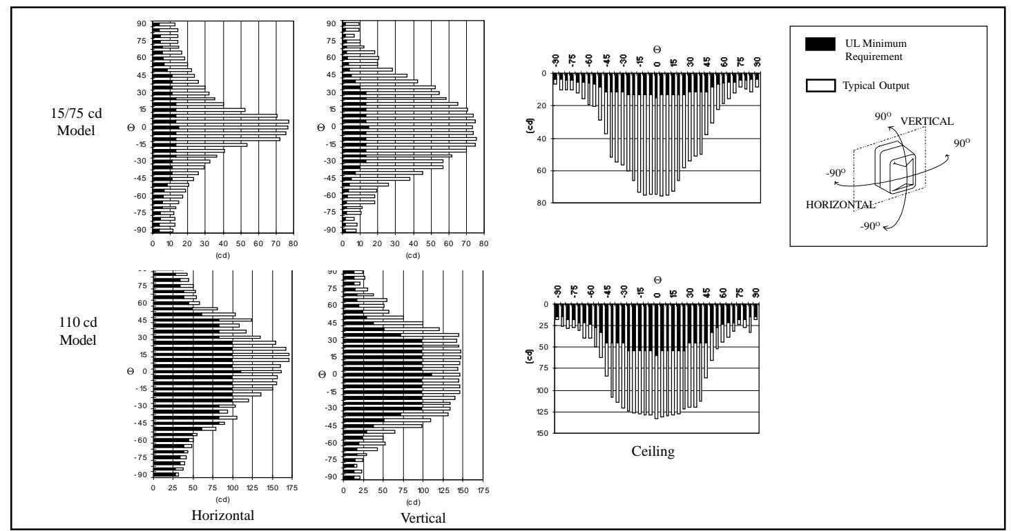
Figure 4. Strobe Light Output Distribution Patterns