Edwards Signaling CBR & WBR Installation Instructions
Open the original PDF document
View PDF

Installation Instructions for AdaptaBeacon® Catalog No. WBR Wall Mount Bracket and Catalog No. CBR Corner Mount Bracket
Description
The Edwards Wall Bracket and Corner Bracket are designed for use with Edwards AdaptaBeacon visual signals having a base suitable for 1/2" (13 mm) or 3/4" (19 mm) conduit mounting.
The CBR Corner Mount Bracket may be used only with surface installed conduit/wiring (see Figure 1). The WBR Wall Mount Bracket may be used with surface installed conduit/wiring (see Figure 2) or with concealed conduit/wiring (see Figure 3).
Installation
The brackets must be installed in acordance with the National Electrical Code (NEC), Canadian Electrical Code (CEC), local code, and the local authority having jurisdiction, and using approved connection means.
Corner Mount (Figure 1)
- 1. Use the corner section of the bracket as a template to mark the positions of the four mounting screws on the mounting surface.
- Drill the four mounting holes at the positions described in 1 (above). Drill size should be determined by the size of the mounting anchors and mounting screws (not supplied) selected.
- Remove the 1/2" (13 mm) knockout from the bottom of the bracket. For indoor applications, install a 1/2" (13 mm) set screw connector and locknut as shown in Detail A. For outdoor applications, use appropriate conduit hardware. A pull box may be used to simplify installation.
- Referring to instructions supplied with the AdaptaBeacon, assemble bracket and secure AdaptaBeacon, routing field ground and power wiring and making ground and power wiring connections appropriately.
The external threaded nipple protruding from the bracket arm is for securing the AdaptaBeacon. A ground terminal is provided for securing ground to the bracket in back of the bracket arm. Two 1/4-20 x 1 1/4" (32 mm) screws are provided to mount bracket arm to the corner section.
NOTE: If the Edwards AdaptaBeacon includes a 3/4" (19 mm) NPT conduit entrance, assemble the 3/4" - 1/2" (19 - 13 mm) reducing bushing to the external threaded nipple protruding from the bracket.

5. Turn on the power to verify that the signal operates properly.
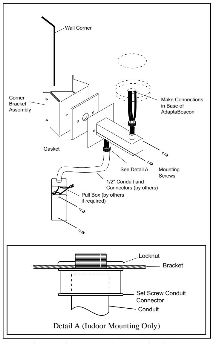
Figure 1. Corner Mount Bracket Surface Wiring
Wall Mount - Surface Conduit/Wiring (Figure 2)
- 1. Use the backplate as a template to mark the positions of the four mounting screws on the mounting surface.
- 2. Drill the four mounting holes at the positions described in 1 (above). Drill size should be determined by the size of the mounting anchors and mounting screws (not supplied) selected. Use oval head screws for mounting.
- 3. Remove the 1/2" (13 mm) knockout in the bottom of the bracket. For indoor applications, install a 1/2" (13 mm) set screw connector and locknut as shown in Detail A of Figure 1. For outdoor applications, use appropriate conduit hardware. A pull box may be used to simplify installation.

WARNING
Do not make power connections within the bracket.
Referring to instructions supplied with the AdaptaBeacon, assemble bracket and secure AdaptaBeacon, routing field ground and power wiring and making ground and power wiring connections appropriately.
The external nipple protruding from the bracket arm is for securing the AdaptaBeacon. A ground terminal is provided for securing ground to the bracket in back of the bracket arm. Two 1/4-20 x 1 1/4" (32 mm) screws are provided to mount bracket arm to the backplate.
NOTE: If the Edwards AdaptaBeacon includes a 3/4" (19mm) NPT conduit entrance, assemble the 3/4" - 1/2" (19-13 mm) reducing bushing to the external threaded nipple protruding from the bracket arm.
5. Turn on the power to verify that the signal operates properly.
Wall Mount - Concealed Conduit/Wiring (Figure 3)
- Mount the backplate to the installed standard 4" (102 mm) square or 4" (102 mm) octagonal electrical outlet box with oval head screws.
- 2. Mount the bracket to the backplate with the two 1/4-20 x 1 1/4" (32 mm) screws provided.
- Referring to instructions supplied with the AdaptaBeacon, assemble bracket and secure AdaptaBeacon, routing field ground and power wiring and making ground and power wiring connections appropriately.
The external threaded nipple protruding from the bracket arm is for securing the AdaptaBeacon. A ground terminal is provided for securing ground to the bracket in back of the bracket arm. Two 1/4-20 x 1 1/4" (32 mm) screws are provided to mount bracket arm to the backplate.
NOTE: If the Edwards AdaptaBeacon includes a 3/4" (19 mm) NPT conduit entrance, assemble the 3/4" - 1/2" (19 mm - 13 mm) reducing bushing to the external threaded nipple protruding from the bracket arm.

Do not make power connections within the bracket.
4. Turn on the power to verify that the signal operates properly.
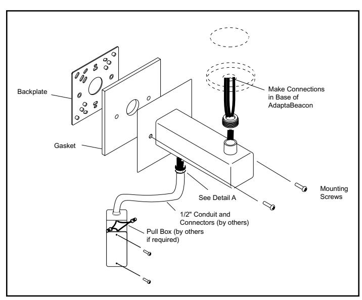
Figure 2. Wall Mount Bracket Surface Wiring
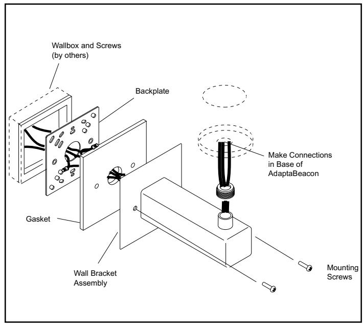
Figure 3. Wall Mount Bracket Concealed Wiring