Edwards Signaling B-KM-8140 B-8141 B-8698 B-8699 Installation Instructions
Open the original PDF document
View PDF

Installation Instructions for Catalog Series B-KM-8140 and B-8141 Explosion Proof Adaptabuzzers and B-8698 and B-8699 Weatherproof Adaptabuzzers
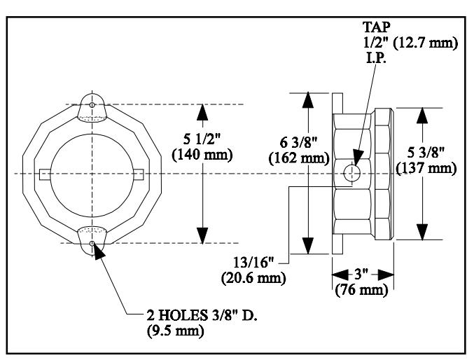
Figure 1. Dimensions
DESCRIPTION
The Edwards Catalog Series B-KM-8140, B-8141, B-8699, and B-8698 Adaptabuzzers are ideal for signaling use in areas where extremely loud signals would be distracting. The B-8698 and B-8699 and CS2690 Adaptabuzzers are gasket sealed, weatherproof units. The B-8699 unit is UL Listed.
ELECTRICAL SPECIFICATIONS
| Catalog Number + | Volts | Amps | VA |
Coil Res.
(ohms) |
| B-KM-8140-E5* | KM-8140-E5* 12 AC 60 Hz | 19.2 | 3.0 | |
| B-KM-8140-G5* | 24 AC 60 Hz | 1.1 | 26.4 | 5 |
| B-KM-8140-N5* | 140-N5* 120 AC 60 Hz | 24 | 146 | |
| B-KM-8140-R5* | 240 AC 60 Hz | .1 | 24 | 740 |
| B-8141-E1* | 12 DC | 1.6 | 19.2 | 3.0 |
| B-8141-G1* | 24 DC | .8 | 19.2 | 21.5 |
| B-8141-P1* | 125 DC | .2 | 25 | 110 |
| B-8141-S1* | 250 DC | .1 | 25 | 600 |
| B-8699-E5* | 12 AC 60 Hz | 1.6 | 19.2 | 1.5 |
| B-8699-G5* | 5* 24 AC 60 Hz | 26.4 | 5 | |
| B-8699-N5* | 120 AC 60 Hz | .2 | 24 | 146 |
| B-8699-R5* | 240 AC 60 Hz | .1 | 24 | 750 |
| B-8698-E1 | 12 DC | 1.5 | 18 | 4.8 |
| B-8698-G1 | 24 DC | 1 | 24 | 21.5 |
| B-8698-P1 | 125 DC | .2 | 25 | 103. |
| B-8698-S1 | 250 DC | .1 | 25 | 600 |
| CS2690 | 125 DC | .2 | 25 | 103 |
+ 75 dB Min at 10 ft
The B-KM-8140 and B-8141 Adaptabuzzers are explosion proof units and are listed for installation in the following hazardous locations:
| Class | Zones | Divisions | Groups |
|---|---|---|---|
| I | 1 and 2 | C and D | |
| I | 1 and 2 | IIA and IIB | |
| II | 1 and 2 | E, F and G |
INSTALLATION
WARNING
To prevent electrical shock, ensure power is off before starting installation.
- 1. Mount the Adaptabuzzer assembly securely to a flat surface in the desired location with (2) screws through the 3/8" (9.5 mm) diameter holes in the housing (Figure 1).
- 2. Remove the unit's cover.
- 3. Install conduit in 1/2" (12.7 mm) NPT tapped hole in side of housing (3/4" (19 mm) NPT optional).
NOTE: Conduit runs must have a sealing fitting connected within 18 inches of the enclosure.
- 4. Using wire nuts, connect the ground wire to the green ground wire attached to the Adatabuzzer housing; connect the incoming power wires to the other two wire leads in accordance with applicable local codes.
- 5. Replace the unit's cover.
MAINTENANCE
WARNING
Ensure that all power is off before performing maintenance.
- 1. Inspect the unit at least once a year for damage or wear.
- 2. Inspect all electrical and mechanical components for internal corrosion or wire discoloration.
NOTE: When reassembling fixture, make certain that the threads and taper joint between housing and brass cover are clean.
* UL Listed