Edwards Signaling B-KM-8130 Series Installation Instructions
Open the original PDF document
View PDF

Cheshire, CT 06410 203-699-3300 (Ph) 203-699-3365 (Cust. Serv. Fax) 203-699-3078 (Tech. Serv. Fax)
Installation Instructions for Catalog Series B-KM-8130 and B-KME-8130 Explosion Proof Horns
Description
The Edwards Catalog Series B-KM-8130 and B-KME-8130 (Projector Units) are intermittent duty explosion proof horns that are ideal for use as call signals in hazardous atmospheres where explosion proof and dust tight features are required. The unit is UL and cUL listed for installation in Class I, Division 2, Groups A and B Temp. Code T4A (248F, 120C); Class I, Divisions 1 and 2, Groups C and D; Class II, Divisions 1 and 2, Groups E, F and G; and Class III, Divisions 1 and 2 hazardous locations.
Electrical Specifications
Intermittent Duty Cycle ....... 5 minutes on/5 minutes off AC Grill Model -- Alternating Current, 60 Hz*
| Cat. No. | Voltage | Current (A) | VA |
Coil
Resistance (ohms) |
|---|---|---|---|---|
| B-KM-8130-G5 | 24V AC | 2 | 48 | 1 |
| B-KM-8130-N5 | 120V AC | 0.45 | 54 | 24 |
| B-KM-8130-R5 | 240V AC | 0.2 | 48 | 103.2 |
| B-KME-8130-NR5 | 120V AC | 0.45 | 54 | 24.4 |
| 240V AC | 0.25 | 60 | 98 |
* The low capacity of bell ringing transformers make them unsuitable for use with low voltage signals. Signaling transformers are required.
Installation

WARNING
To reduce the risks of electrical shock and ignition of hazardous atmospheres, do not apply power until the unit installation has been completed and unit is tightly assembled and secured.
These products are intended to be installed in accordance with the applicable requirements in the latest editions of either the National Fire ProtectionAssociation publication NFPA 70, the National Electrical Code, or the Canadian Standards Association publication C22.1-02, the Canadian Electrical Code, Part I, and in accordance with the local authorities having jurisdiction.
- 1. Mount the horn assembly securely to a flat surface in the desired location with (2) screws through the 3/8" (9.5 mm) diameter holes in the housing. See Figure 1.
- 2. Install conduit in 1/2" (12.7 mm) NPT tapped hole in side of housing.
NOTE: Conduit runs must have a sealing fitting connected within 18 inches of the enclosure.
- 3. Connect wires (2 for B-KM Series or 4 for B-KME Series) using wire nuts (supplied) in accordance with applicable local codes (Figure 2).
- 4. For B-KM-8230 Series, connect green ground wire to external ground.
Maintenance

WARNINGS
To reduce the risk of equipment damage and ignition of hazardous atmospheres, keep the assembly tightly closed when circuits are energized.
Ensure that all power is off before performing maintenance.
- 1. Check and inspect the unit at least once a year for damage or wear
- 2. Inspect all electrical and mechanical components to see if there is any internal corrosion or wire discoloration.

CAUTION
When reassembling fixture, make certain that the threads and taper joint between housing and brass cover are clean.
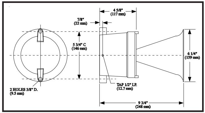
Figure 1. Single Projector Unit (B-KM-8130 Series)
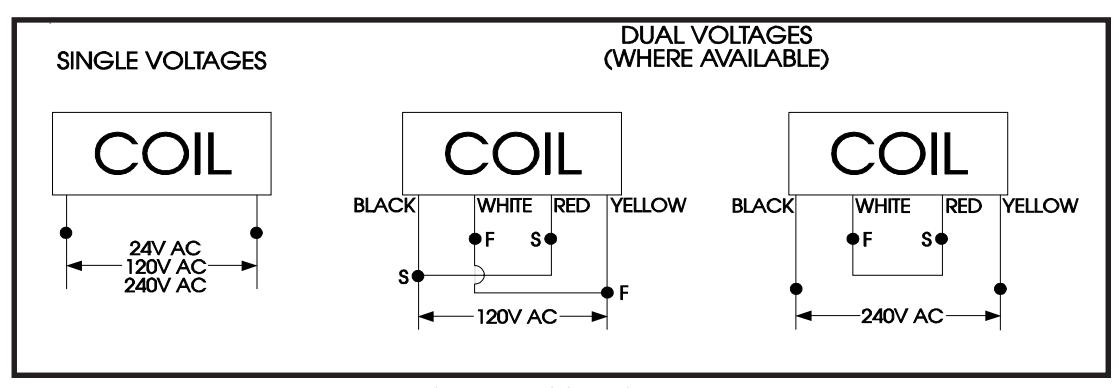
Figure 2. Wiring Diagrams