Edwards Signaling B-ER Series Installation Instructions
Open the original PDF document
View PDF

Installation Instructions for Catalog Numbers B-ER-1000, B-ER-2000, B-ERW-2100, B-ERX-2100 Electronic Telephone Relays
DESCRIPTION
The Edwards electronic telephone relays are available in four models: Modular Indoor (Cat. No. B-ER-1000), Hardwire Indoor (Cat. No. B-ER-2000), Hardwire Weatherproof (Cat. No. B-ERW-2100), Hardwire Explosion-Proof (Cat. No. B-ERX-2100). The units are for use with horns, bells, strobes or similar devices to create a remote signal extension that matches the telephone ringing cycle. The relays are activated by ordinary ringing voltage of the telephone.
- These devices are intended for connection to single line telephone or key systems only. They are not intended for use on "party line" or on coin telephone lines.
- When installed in accordance with these instructions, the devices can be readily disconnected without affecting equipment remaining on the telephone network.
- Registered with the Federal Communications Commission in compliance with Part 68 of FCC Rules and Regulations.
- UL Listed.
IMPORTANT TELEPHONE INFORMATION
The following information may be required by the telephone company: Telephone Number, FCC Registration Number: 3Z9USA-21250-RG-N.
The Ringer Equivalence Number (REN) allows the installer to determine the number of devices that can be added to the telephone line and still have all the devices ring when the number is called. In most but not all areas, the sum of all RENs for all devices connected to your line should not exceed five. To be sure of the number of devices you can connect to your telephone line, contact your local telephone company.
If these devices damage the telephone network, the telephone company will notify the owner that it may temporarily disconnect service if they consider such action necessary. If the owner considers the disconnection unwarranted, they have the right to bring a complaint to the FCC.
The telephone company may make changes in its communication facilities, equipment, operations, or procedures when such action is required. If these changes render the devices incompatible with the telephone company facilities, the telephone company will provide enough written notice so that necessary changes can be made in order to maintain uninterrupted service.
ELECTRICAL SPECIFICATIONS
| Cat. No. | Description |
Input
Voltage |
Max. Switching
Voltage |
Max Amps
Switch |
REN |
|---|---|---|---|---|---|
| B-ER-1000 |
Modular
Indoor |
40-150 AC
16-70 Hz |
120 AC | 3.0 | 3.7B |
| B-ER-2000 |
Hardwire
Indoor |
10-250 AC
16-70 Hz 10-150 DC |
120 AC | 5.0 |
1.5B (>50V)
3.4B (<50V) |
| B-ERW-2100 |
Hardwire
Watertight |
10-250 AC
16-70 Hz 10-150 DC |
120 AC | 5.0 |
1.5B (>50V)
3.4B (<50V) |
| B-ERX-2100 |
Hardwire
Explosion Proof |
10-250 AC
16-70 Hz 10-150 DC |
120 AC | 5.0 |
1.5B (>50V)
3.4B (<50V) |
INSTALLATION
NOTE: Telecommunication wiring which is connected to either the B-ER-1000 or B-ER-2000 relay shall not extend outside the building that the relay module is contained in.
Modular Indoor Unit (Figure 1)
NOTE: This device is for indoor use only with telephones having modular (RJ11C type) jacks.
- 1. Connect modular plug telephone line cord into modular jack on bottom of electronic relay.
- 2. Insert power cord of signal device to receptacle on side of electronic relay.
- 3. Plug unit into 120V, 60Hz wall outlet.
- 4. Connect signaling devices to 120V outlet on relay. Verify operability of electronic relay.
Hardwire Indoor Unit (Figure 2)
- 1. Remove the four screws securing the relay housing cover to the relay housing and remove the relay housing cover.
- 2. Mount relay housing on flat surface using the 2 screws provided.
- 3. Wire as shown in Figure 4.
- 4. Secure relay housing cover to relay housing using the four screws removed in Step 1.
Weatherproof and Explosion Proof Units (Figure 3)
- 1. Unscrew and remove the relay housing cover.
- 2. Mount relay to selected surface using the cast ears. Carefully orient the unit hubs with respect to the direction of incoming and outgoing conduit wiring.
- 3. Attach incoming and outgoing conduit to relay housing and wire as shown in Figure 4.
- 4. Screw relay housing cover back onto relay housing. Tighten to sufficiently establish the gasketed integrity of the unit.
P-047550-1610 ISSUE 1
© 1995

MAINTENANCE
CAUTION
This unit is not serviceable or repairable. Should the unit fail to operate, contact the supplier for replacement.
If this product should fail to operate, disconnect it from the telephone line and determine if the problem is in the telephone line or the device. If this product is defective, discontinue its use and obtain a replacement.
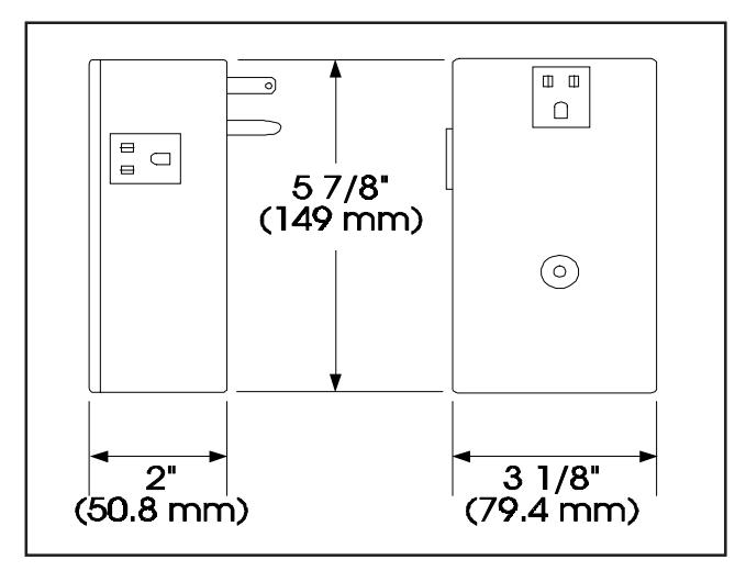
Figure 1. Modular Indoor Unit
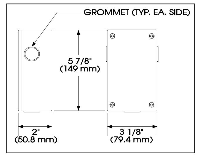
Figure 2. Hardwire Indoor Unit
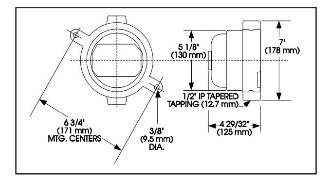
Figure 3. Weatherproof and Explosion Proof Units
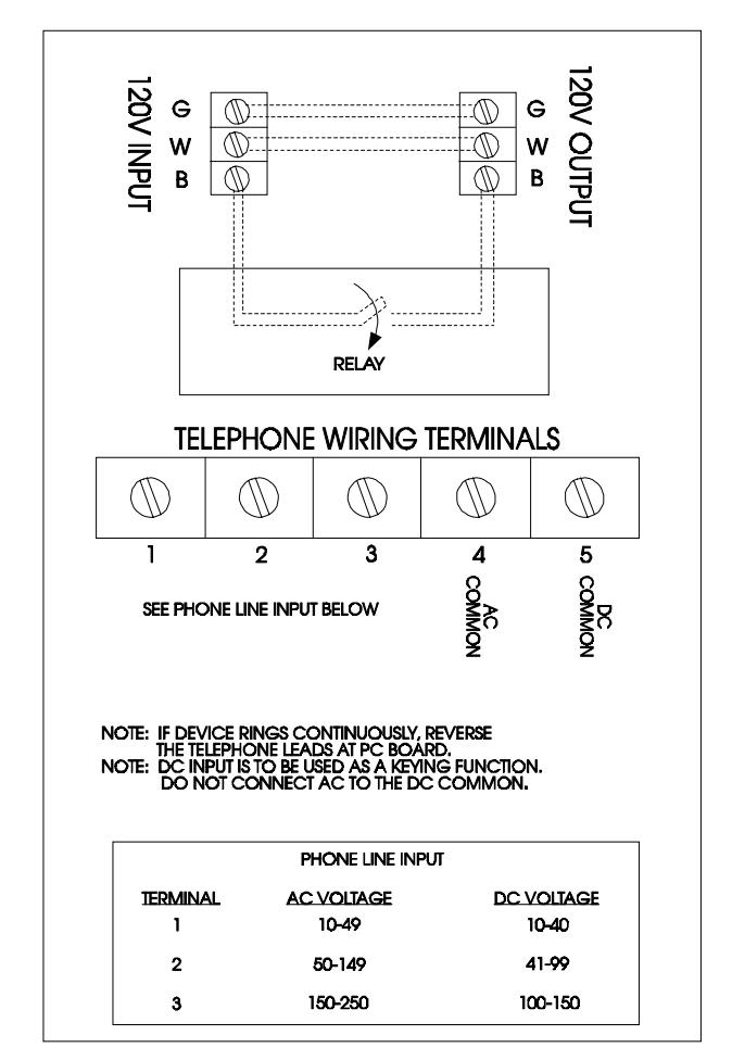
Figure 4. Electrical Connections