Edwards Signaling AE Bulletin Elevator Recall & E-FSA Update
Open the original PDF document
View PDF


AEBN: 020812
Date: February 8, 2012
Subject: Elevator Control and E-FSA Addressable Panel - Update
Introduction
This bulletin is an update to a previous one (AEBN 022410) describing how you can perform elevator control using the Edwards E-FSA addressable fire alarm system.
To review: The idea behind elevator recall is to bring the elevators to the lowest safe floor for exit during a fire so that people on the elevator do not step out into a smoke filled lobby. This will also make the elevators available to emergency personnel. To accomplish this, smoke detectors are located in the elevator lobbies of a building. If one of those smoke detectors alarm, the elevator will be sent to the proper floor. That floor will depend on which smoke detector went into alarm.
For example, if a smoke detector in the lobbies of the upper floors (2 and above) alarm, the elevator will be recalled to the designated (primary) level (usually the first floor). If a detector in the elevator lobby of the designated level alarms, the elevator will be recalled to an alternate level (usually the second floor). In addition to smoke detectors in lobbies, detectors are installed in the elevator machine room (and sometimes elevator shaft), which also recall the elevators. The machine room and shaft smoke detectors will also turn on a visual warning signal ("fireman's hat") located in the elevator or elevator lobbies, indicating the elevator is not safe to use. All these smoke detectors would be programmed to activate relays located in the elevator machine room that are used to control the elevators and turn on the warning light.
In buildings where the elevator shaft and/or machine room is protected by automatic sprinklers, a shunt trip circuit breaker is required to disconnect power to the elevator prior to the sprinkler heads in these areas activating. This is initiated by a heat detector located near the sprinkler head (or in some cases a waterflow switch with no delay) to insure the elevators shut down to prevent any further use of them. The heat detector(s) or waterflow switch then activate a relay, also located in the elevator machine room, used to trip the breaker. In addition, the power used to activate the shunt trip breaker must be supervised. The sprinkler system itself would also have to be monitored by the fire alarm panel.
The following will show a description of operation, a recommended parts list, and programming examples using the FSA-CU configuration utility program.


Elevator Block Diagram
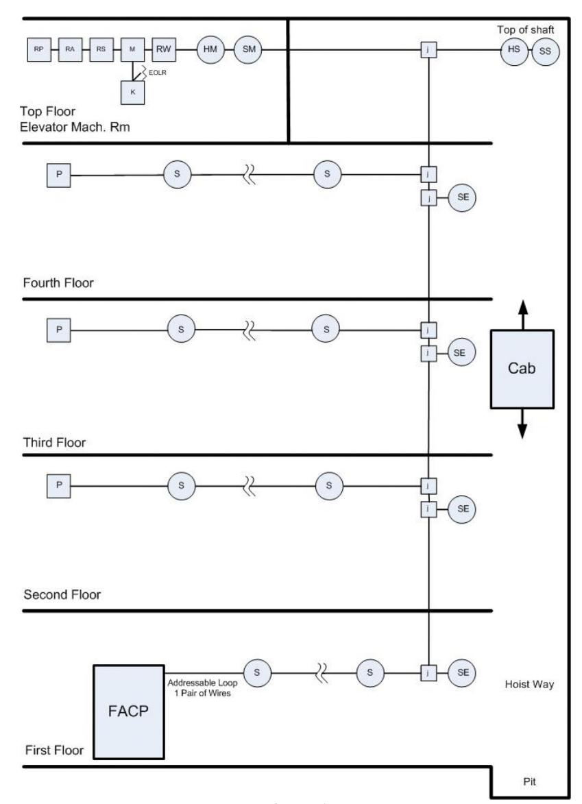
Figure 1
Legend:
- 1. SE = smoke detectors in elevator lobbies
- 2. SM = smoke detector in elevator machine room
- 3. SS = smoke detector in elevator shaft
- 4. HM = heat detector in elevator machine room
- 5. HS = heat detector in elevator shaft
- 6. RP = relay for primary recall
- 7. RA = relay for alternate recall
- 8. RS = relay for shunt trip
- 9. RW = relay for elevator warning
- 10. K = relay for monitoring shunt trip breaker power
- 11. M = module to monitor shunt trip (K) relay
- 12. P & S = other pulls and smokes throughout building (not part of elevator control)
- 13. Module for monitoring sprinkler system not shown


Description of Operation
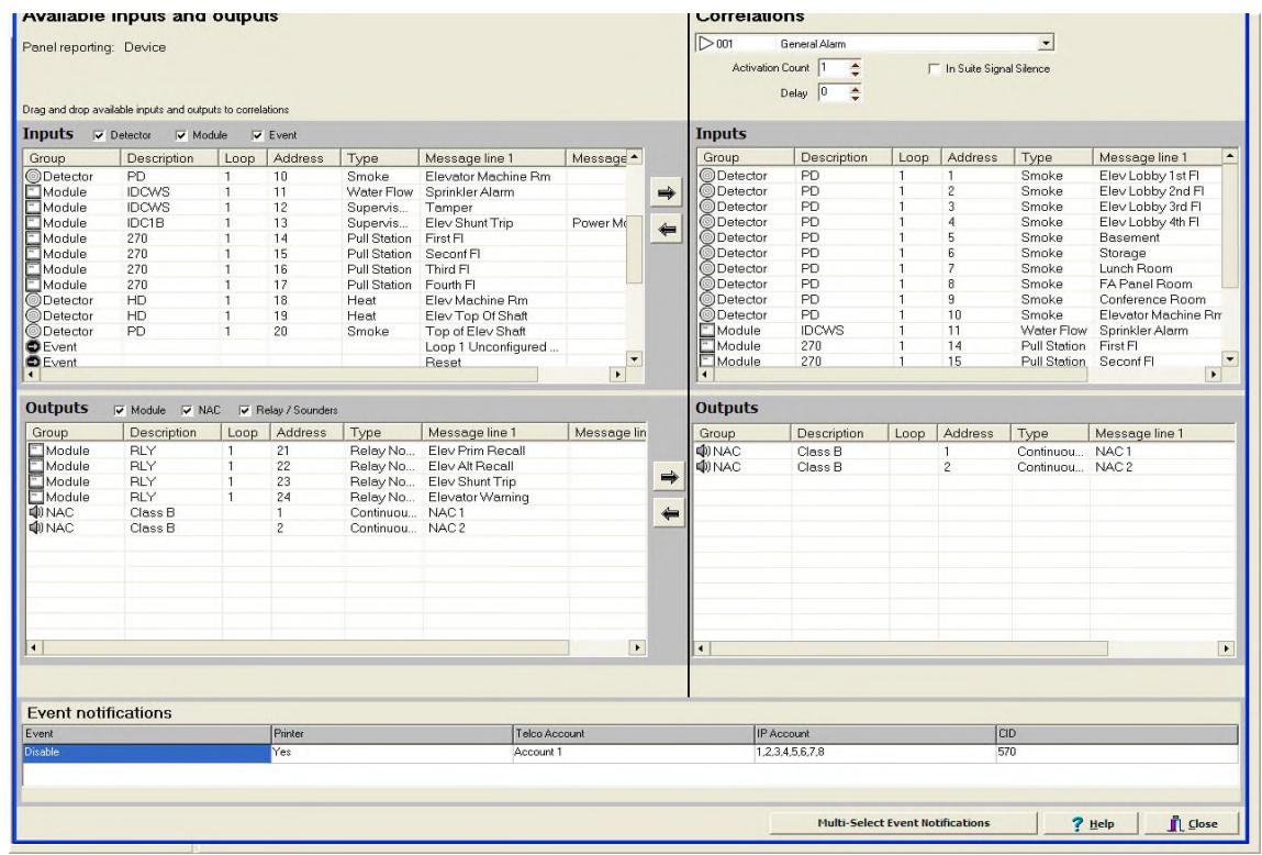
- For this example it will be assumed the system is programmed for general alarm operation using Correlation Group 1 (figure 2). Actual Correlation Group numbering may be different than what is used here.
- Correlation Group 2 (figure 3) will be created for alternate floor recall and will include the SE smoke detector in the first floor elevator lobby and the RA alternate floor recall relay. When this smoke detector activates, the elevator will be recalled to the alternate floor.
- Correlation Group 3 (figure 4) will be created for primary recall and will include all the SE smoke detectors on floors 2 and up plus the primary floor recall relay RP. When any one of these smokes activate, the elevator will be recalled to the primary level.
- Smoke detectors in the elevator machine room (SM) and elevator shaft (SS), if used, will be added to Correlation Group 2 or 3, depending on which floor the elevator should be recalled to (first floor in this example, figure 4).
- If a heat detector is located in the elevator machine room (HM) and/or elevator shaft (HS), Correlation Group 4 (figure 5) will be created which will include these heat detectors along with the RS elevator shunt trip relay. Activation of any of these heats will break power to the elevator. Note: if a delay is required to bring the elevator to the lowest recall level prior to the shunt trip, this can be set from 0 to 300 seconds in programming.
- Correlation Group 5 (figure 6) is used to activate the elevator warning light relay (RW) if the elevator machine room (SM) or elevator shaft (SS) smoke detectors alarm.
- The module (M) will be configured as a supervisory input and wired to the K relay's normally closed (open while energized) contact. The relay's coil will be powered from the same source used to activate the shunt trip breaker.
- The smoke detectors in the elevator lobbies, machine room, and shaft along with the heat detectors shown will also usually be part of Correlation Group 1 for general alarm evacuation. The relays for elevator recall, warning, and shunt trip will not be included in Correlation Group 1.
Parts List (using E-FSA system)
- Fire alarm panel: E-FSA64 or E-FSA250 addressable panel
- Smoke detectors for elevator lobbies, machine room, shaft: E-PD plus B4U base.
- Heat detectors for elevator machine room and elevator shaft: E-HD plus B4U base or 283B-PL wired to E-IDC1B or E-IDC2B module (E-HD configured for fixed temp).
- Module for sprinkler monitoring: E-IDCWS . Note: Waterflow input has a built in, nonadjustable 16 second delay. If a delay is not desired, you can use an E-IDC1B or E-IDC2B module configured for Alarm input device type.
- Addressable relays for elevator recall, warning, and shunt trip: E-RLY . Note: if load exceeds contact rating of E-RLY, you will have to interpose a second relay with higher contact ratings.
- Monitor module (M) for shunt power relay supervision: E-IDC1B .
- Relay for shunt trip power supervision (K): PAM-1 or MR101/C.


Correlation Group Examples (FSA-CU)
General Alarm Correlation
Figure 2
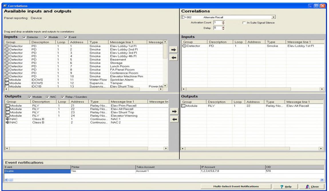
Alternate Recall Correlation
Figure 3


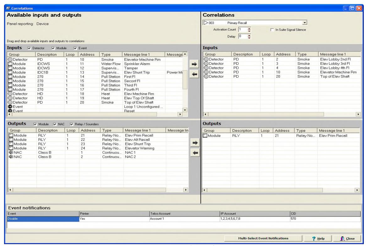
Primary Recall Correlation
Shunt Trip Correlation
Figure 4
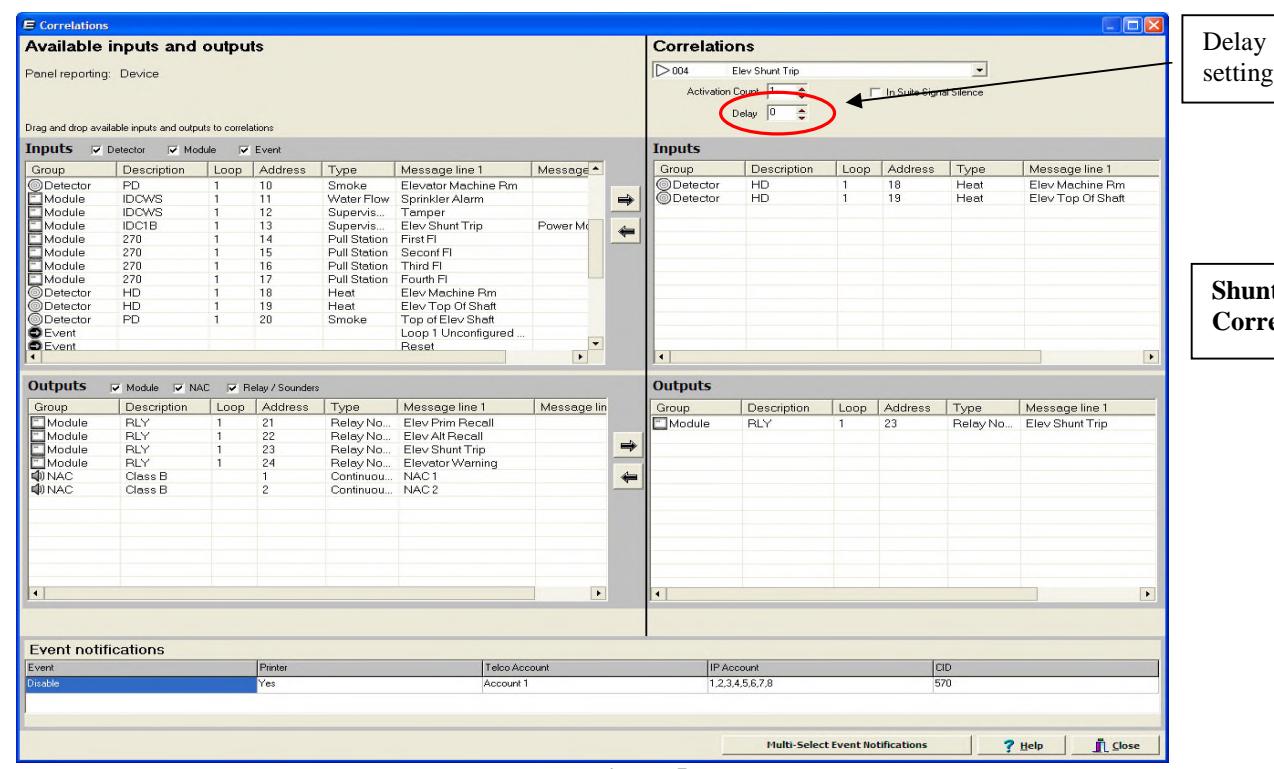
Figure 5


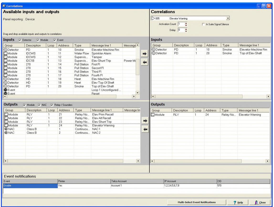
Elevator Warning Correlation
Figure 6
It is not the intent of this bulletin to cover all the details of what the codes require for proper elevator control. For that you should refer to the appropriate national and local codes, such as the ASME A17.1 Safety Code for Elevators and Escalators and NFPA 72 National Fire Alarm and Signal Code . This bulletin was written to describe one way to implement the most common method of elevator control using the Edwards E-FSA addressable system.