Edwards Signaling AE Bulletin ANS Backup Amplifier
Open the original PDF document
View PDF


AEBN: 120210-7
Date: December 2, 2010
Subject: Fire Alarm Voice Evacuation with Backup Amplifier
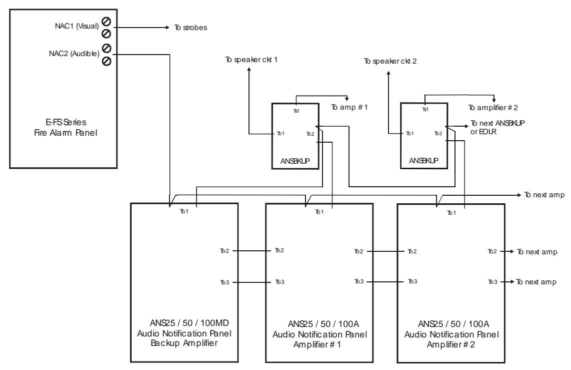
The ANSBKUP module is used to switch in a backup amplifier in the event of a primary or expander amplifier failure. You can use one backup amplifier to support one or several other amplifiers, with each backed up amplifier requiring an ANSBKUP module. The backup amplifier should be at least as large as the largest amplifier in the system. For example, if you have two 25 watt amplifiers and one 50 watt, the backup amplifier should be 50 watts or more. The backup amplifier should also be the one that includes (if required) the paging microphone and digital message player. Its low level audio is always fed to the preamp inputs of the other amplifiers. The high level audio to the speakers only gets switched in when needed.
Below is a simplified block diagram of a system with a backup amplifier, followed by a more detailed diagram showing the connections with just one amplifier. Neither diagram shows all the necessary connections, however, so be sure to refer to the installation drawings for more information.
Block Diagram of Voice Evacuation with Backup Amplifier
Edwards Signaling, Part of UTC Fire & Security – 41 Woodford Ave., Plainville, CT, 06062 Phone: 800-336-4206 – Web: www.edwardssignaling.com - E-mail: signaling.techsupport@fs.utc.com


Wiring Diagram of Voice Evacuation with Backup Amplifier
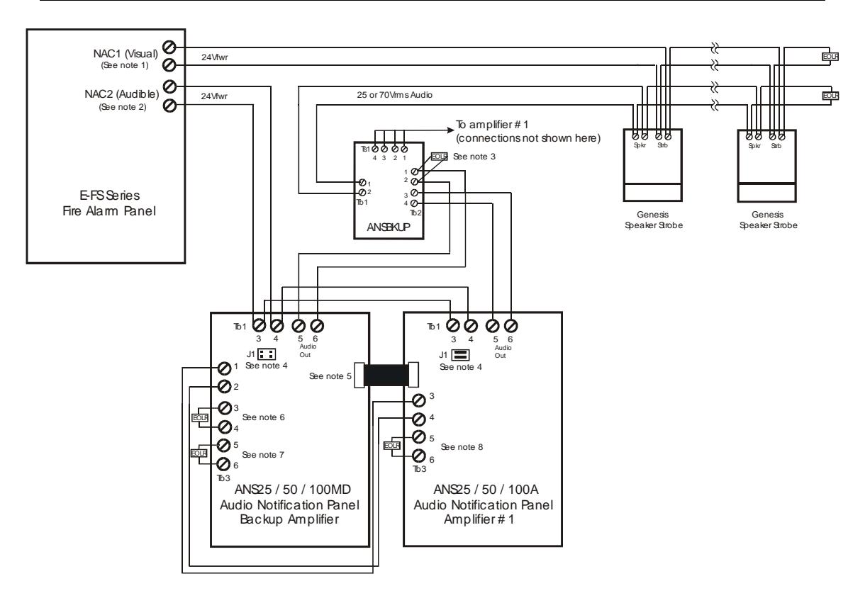
Notes:
- 1. NAC1 on fire alarm panel should be configured as Genesis.
- 2. NAC2 on fire alarm panel should be configured as Continuous.
- 3. End of line resistor for backup amplifier circuit. If multiple ANSBKUPs, resistor would go on last module. Value of resistor must match the resistor used on terminals Tb3: 5 & 6 of the backup amplifier (see note 7).
- 4. Jumpers on J1 shorting pins must be installed only on the amplifier farthest (electrically) from the backup amplifier.
- 5. Ribbon cable may be used if both amplifiers are mounted in the same cabinet. Refer to installation instructions for further details on interconnecting amplifiers. Could also use Tb2 connections (not shown here).
- 6. End of line resistor value here must match value used for NAC circuit on fire alarm panel. For FS series, it's 4.7K ohms.
- 7. End of line resistor value here must match value used on ANSBKUP (see note 3).
- 8. End of line resistor value here must match value used for speaker circuits' EOLR. For example, if speaker circuit is using a 10K ohm eol resistor, the resistor connected here must be 10K ohms. Value of resistor can be between 2.2k and 100K ohms.