Edwards Signaling 970522 Technical Bulletin
Open the original PDF document
View PDF


Edwards Signaling Products 90 Fieldstone Court Cheshire, CT 06410 (203) 699-3300 FAX (203) 699-3108
Technical Bulletin # 970522
Date: August 9, 1999 Product: Message Centers Product Category: PLC Activation
Subject: Activating Messages using a Dry Contact Closure
Every Edwards Message Center is capable of displaying messages using an ASCII Text string. This technical bulletin will demonstrate how to activate messages previously loaded into your Edwards Message Center utilizing a Dry Contact Closure . This method is very similar to Technical Bulletin 970521, in that a PLC is used to send an ASCII Text String to the Message Center. The PLC needs to be capable of sending this string to either an RS232 or RS485 output on the PLC. The text string must also be in the proper format; otherwise the message will not be displayed. Any Experienced Ladder Logic Programmer will understand these basic instructions and will be able to integrate these commands into more complex Ladder Logic Functions.
SECTION I: Application Example:
An end user wishes to monitor several limit switches. When a limit switch is activated, they wish to display a text message on an Edwards Message Center. This can be accomplished using a PLC that is capable of outputting an ASCII text string. The PLC can then be programmed to output the ASCII Command code to turn on a message like, "Low Level in Tank 12". Also, an audible or visual signal could be activated at the same time if the PLC has Relay outputs. This is ideal for drawing attention to an important message that is being displayed on the Edwards Message Center.
This is a basic way to operate a Message Center using Dry Contact Inputs. Once again, an experienced programmer will be able to program their PLC for this type of operation and will be able to perform more complicated operations. Also, the desired messages must be programmed ahead of time into the Edwards Message Center.
SECTION II: Hardware Connections
The type of contact (Momentary or Maintained) will need to be determined by the input requirements of the PLC in use. Also, the PLC Software must be capable of sending an ASCII Text String to an RS232 Serial Port. For single Message Center operation use an adapter and straight through RS-232 cable as shown in diagram 1. For multiple Message Center or RS485 operation follow the wiring employed in diagram 2. Another use of the PLC is to use Output cards to control a signaling device when a message is being displayed, diagram 3. An example may be to have a horn sound or a light flash to alert personnel that an important message is being displayed. Generally, PLC output cards have the option of either a relay output or a source voltage. Either option can be used when Edwards Process Control Signals are utilized.
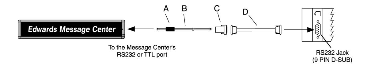
| Item | Cat. No. | Description | ||
|---|---|---|---|---|
| A | — | Ferrite (ferrite end towards Message Center) | ||
| B | MCN232-RJ11-25 | 25 foot, 6-conductor RS-232 cable | ||
| MCN232-RJ11-50 | 50 foot, 6-conductor RS-232 cable | |||
| C | MCN2329FRJ11 | 9 Pin D-Sub/to 6 pos RJ11 adapter | ||
| D | MCN485CB232A9 | 10 foot 9 pin-to-9pin type A9 RS232 cable | ||
| NOTE: Set internal message center jumper to RS232 | ||||
Diagram 1
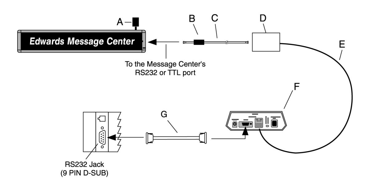
| Item | Cat. No. | Description | ||||
|---|---|---|---|---|---|---|
| A | MCN485EOLTCB | EOL Termination | ||||
| B | — | Ferrite (ferrite end towards Message Center) | ||||
| C | MCN232-RJ11-8 | 8 foot, 4-conductor RS-485 cable | ||||
| MCN485-RJ11-1 | 1 foot, 4-conductor RS-485 cable | |||||
| D | MCNMNARJ11485 | Modular network adapter | ||||
| E | MCN485-1000 | 1000 foot spool of RS485 cable | ||||
| F | MCN485CB2EOLT | Converter box w/2 EOL terminators | ||||
| G | MCN485CB232A9 | 10 foot 9 pin-to-9 pin type A9 RS232 cable | ||||
| NOTE: Set internal message center jumper to RS485 | ||||||
Diagram 2
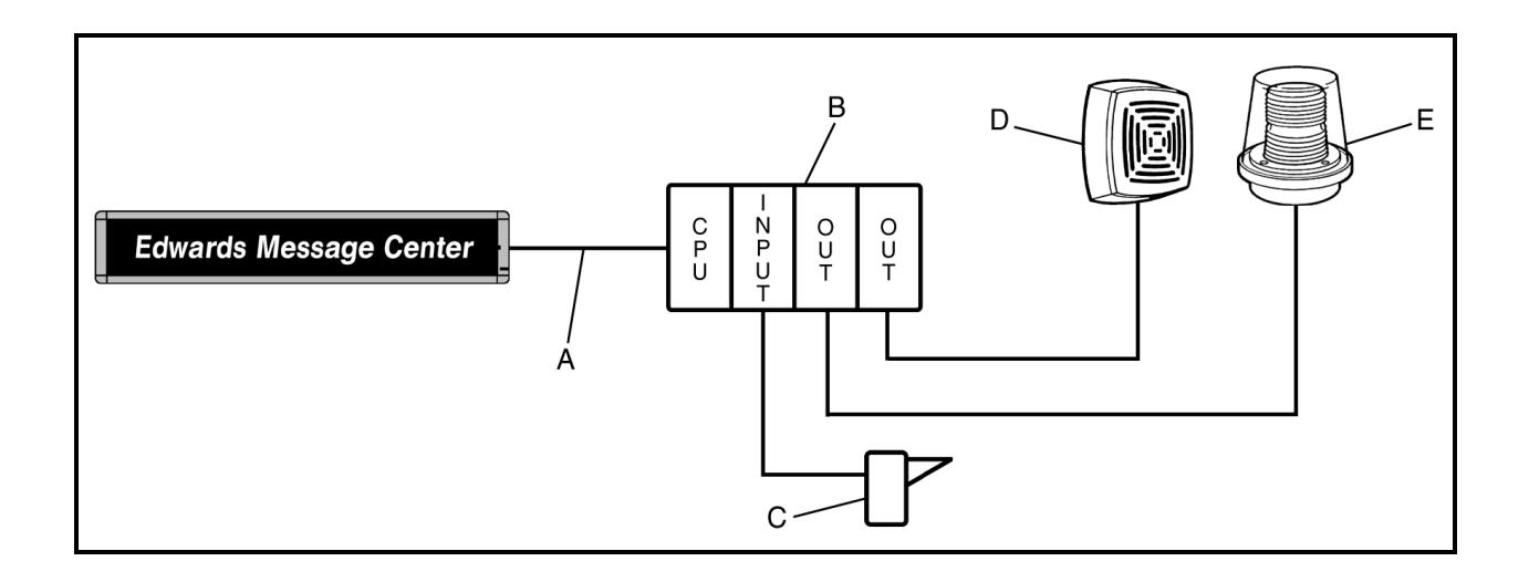
| Item | Description | |
|---|---|---|
| A | RS232 Cable from PLC to the Edwards Message Center | |
| B | PLC (A Basic PLC consists of the CPU, Input and Output Cards) | |
| C |
Contact Device (PLC's have different input requirements, this
contact device may be Normally Open |
|
| D | Edwards Audible Signal (See your Edwards Catalog) | |
| E | Edwards Visual Signal (See your Edwards Catalog) | |
Diagram 3
SECTION III: Software Configuration
To configure any software for communications with the Message Center, the following parameters need to be established by the user. The Message Center will not receive any data transmitted faster than 9600 Baud.
Mode: ASCII Baud: 9600 Parity: None Stop Bits: 1 Start Bits: 8
SECTION IV: Message Center Setup
Messages must be loaded into the Message Center using any of the 81 valid File labels. Refer to your Remote Control Programming Instructions or Technical Bulletin 970520 for information on loading messages into your Edwards Message Center.
SECTION V: Text String Format
Sending an ASCII text string to a Message Center can easily activate any message saved in the Message Center's memory. Listed below is a sample string that instructs an Edward's Message Center to display a preloaded message : The Message Center's serial address in this example is 01.
Note - Each message string should begin with five NUL (00h) characters for auto-baud detect of serial data sent to the Message Center. Messages should follow the Special Function Text Format outlined below:
Message example 1:
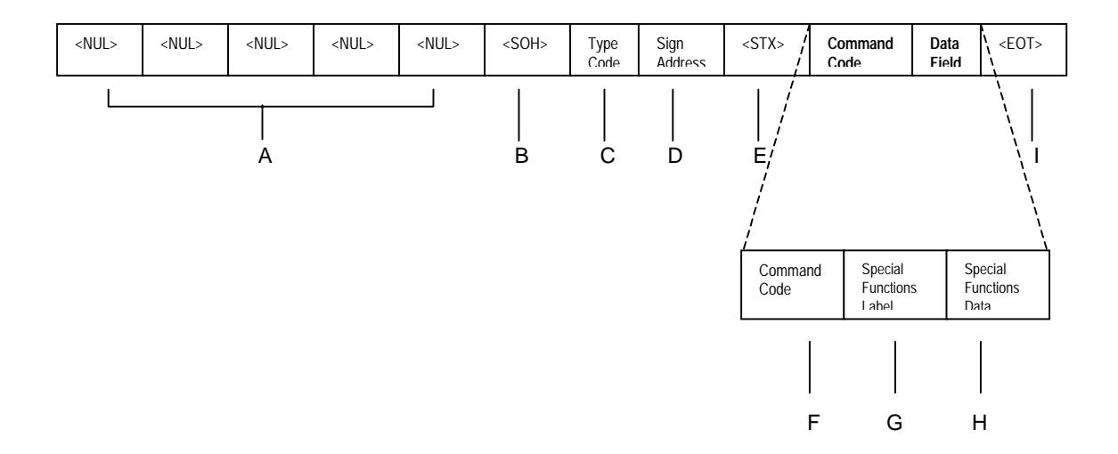
<NUL><NUL><NUL><NUL><NUL><SOH>Z01<STX>E.SUA<EOT>
Where:
| Item | Name | ASCII | HEX Value | Description | ||
|---|---|---|---|---|---|---|
|
|
^@ | 00h |
Five consecutive
|
|||
| A | message. | |||||
| B |
|
^A | 01h |
|
||
| C | Type Code | Z | 5Ah | ASCII Type Code for All Signs in network | ||
| D | Sign Address | 01 | 30h | 31h | 2 Byte ASCII-Hex Sign Address (see note 1) | |
| E |
|
^B | 02h |
|
||
| F | Command Code | E | 45h | Command code E, Write Special Functions to the sign | ||
| G | Special Functions Label | 2Eh | Set Run Sequence | |||
|
Special
Functions Data |
Run Sequence Order | T or S | 54h or 53h |
"T" 54h = All subsequent Text File Labels in the run
sequence will run according to their associated times. "S" 53h = All subsequent Text File Labels in the Run Sequence will run in order regardless of each file's run time. |
||
| H |
Keyboard Protection
Status |
U or L | 55h or 4Ch |
"U" 55h = Unlocked. This allows the Run Sequence to be
changed from the Handheld Remote. "L" 4Ch = Locked. The Run Sequence is inaccessible from the Handheld Remote. |
||
| Text File Label | A, B, etc. | 41h, 42h, etc. |
Text Files to be activated. More than one file can be
specified. This also determines the run order. |
|||
| I |
|
^D | 04h |
The
end of every message string. |
||
Note: The serial address of the Message Center is represented by two ASCII digits as a number between "00" to "FF" (0 to 255). If 00 is the desired serial address, the two byte ASCII representation would be 30h for the first digit and 30h for the second digit. It is important to
remember to treat the serial address as a two-digit code. (All Message Centers on the network will respond to the string when the serial address is 00.)
SECTION VI: Sample Strings
| Message Action | String Required |
|---|---|
| Activate Text File A |
|
| Activate Text File B |
|
| Activate Text File C |
|
| Activate Text Files A, B & C |
|
Note: The Run Sequence Order is determined by the order of the File Labels as entered into the text string.
SECTION VII: Additional Support
For questions please call our Technical Support @ 203-699-3300 or visit our website www.edwardssignals.com. Additional codes are available for controlling message center text strings in our Communications Protocol available from your local Edwards Signaling representative.