Edwards Signaling 970520 Technical Bulletin
Open the original PDF document
View PDF


Edwards Signaling Products 90 Fieldstone Court Cheshire, CT 06410 (203) 699-3300 FAX (203) 699-3108
Technical Bulletin # 970520 Date: July 19, 1999 Product: Message Centers Product Category: PLC Activation
Subject: How to display text messages using a PLC
All Edwards Message Centers are capable of displaying messages using an ASCII Text string. This bulletin will describe the steps necessary to use a PLC to display basic messages on any Edwards Message Center. The PLC needs to be capable of sending an ASCII Text String to either an RS232 or RS485 output. The text string must be in the proper format; otherwise the message will not be displayed. Any Experienced Ladder Logic Programmer will understand these basic instructions and will be able to integrate these commands into more complex Ladder Logic Functions.
SECTION I: Hardware Connections
The PLC Software must be capable of sending an ASCII Text String to an RS232 Serial Port. For single Message Center operation use an adapter and straight through RS-232 cable as shown in diagram 1. Or for multiple Message Centers or RS485 operation you should follow the wiring employed in diagram 2.
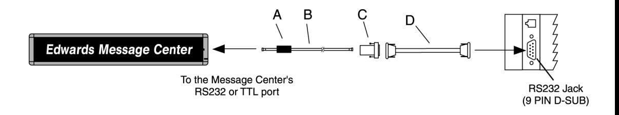
| Item | Cat. No. | Description | ||
|---|---|---|---|---|
| A | — | Ferrite (ferrite end towards Message Center) | ||
| B | MCN232-RJ11-25 | 25 foot, 6-conductor RS-232 cable | ||
| MCN232-RJ11-50 | 50 foot, 6-conductor RS-232 cable | |||
| C | MCN2329FRJ11 | 9 Pin D-Sub/to 6 pos RJ11 adapter | ||
| D | MCN485CB232A9 | 10 foot 9 pin-to-9pin type A9 RS232 cable | ||
| NOTE: Set internal message center jumper to RS232 | ||||
Diagram 1
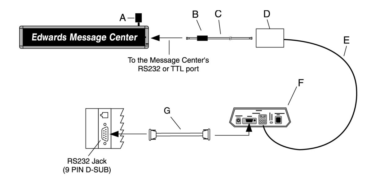
| Item | Cat. No. | Description | ||
|---|---|---|---|---|
| A |
MCN485EOLTCB
EOL Termination |
|||
| B | — | Ferrite (ferrite end towards Message Center) | ||
| C |
MCN232-RJ11-8
8 foot, 4-conductor RS-485 cable |
|||
| MCN485-RJ11-1 | 1 foot, 4-conductor RS-485 cable | |||
| D | MCNMNARJ11485 | Modular network adapter | ||
| E | MCN485-1000 | 1000 foot spool of RS485 cable | ||
| F |
MCN485CB2EOLT
Converter box w/2 EOL terminators |
|||
| G | MCN485CB232A9 | 10 foot 9 pin-to-9 pin type A9 RS232 cable | ||
| NOTE: Set internal message center jumper to RS485 | ||||
Diagram 2
SECTION II: Software Configuration
To configure any software for communications with the Message Center, the following parameters need to be established by the user:
Mode: ASCII Baud: 9600 Parity: None Stop Bits: 1 Start Bits: 8
SECTION III: Message Center Setup
There are only a few things needed to set up the Message Center to receive text strings from the PLC. First, set the internal jumper to RS-232 or RS-485 position as needed. Next, Clear the Message Center's memory and setup the desired serial address using the remote control.
The serial string to clear memory is: <NUL><NUL><NUL><NUL><NUL><SOH>Z01<STX>E$AAU0100FF00<EOT> This string sets the Message Center's memory configuration for File Label A, Write a Text File, Unlocked (File is accessible using Remote Control), File Size 0100h (256 bytes, 4 byte format), Start Time = FF (Run always, two byte format), and Stop Time = 00 (Stop time is ignored when message is set to run always, two byte format).
SECTION IV: Text String Format
A message can easily be constructed by typing directly in ASCII to the appropriate data source file. Listed below is a sample string that tells an Edward's Message Center to display the following text and format : "Electrician and Supervisor report to cell #3 " with Fill text, Red text color, normal font, in hold text mode. The Message Center serial address in this example is 01.
Message example 1:
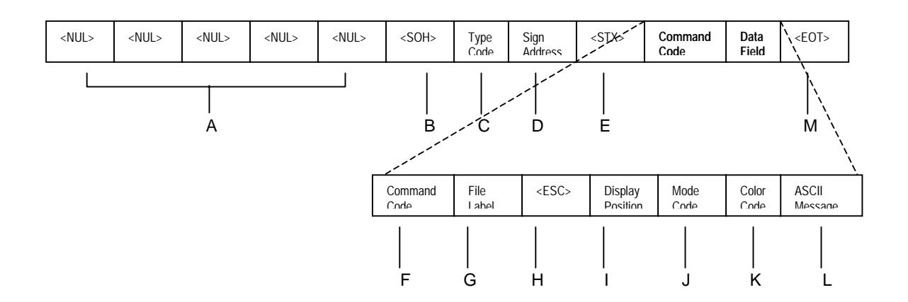
<NUL><NUL><NUL><NUL><NUL><SOH>Z01<STX>AA<ESC>0b<FS>1Electrician and Supervisor please report to cell #3<EOT>
Where:
| Item | Name | ASCII | HEX Value | Description | ||||
|---|---|---|---|---|---|---|---|---|
| A |
|
^@ | 00h |
Five consecutive
the message. |
||||
| B |
|
^A | 01h |
|
||||
| C | Type Code | Z | 5Ah | ASCII Type Code for All Signs in network | ||||
| D | Sign Address | 01 | 30h | 31h | 2 Byte ASCII-Hex Sign Address (see note 1) | |||
| E |
|
^B | 02h |
|
||||
| F | Command Code | A | 41h | Command code A, Write a TEXT File to the sign | ||||
| G | File Label | A | 41h | File Label A name | ||||
| H |
|
^[ | 1Bh |
The
Mode Field |
||||
| I |
Display
Position |
0 | 30h | Display position. (see note 2) | ||||
| J |
Data
Field |
Text
File Format |
Mode
Field |
Mode
Code |
b | 62h | A control character that denotes holding the text in place | |
| K |
Color
Code ( "color") |
^\ + 1 | 1Ch | 31h |
A 2 byte control character that tells the sign to use Red
text. (see note 3) |
|||
| L |
"Electrician and
ASCII Text Message Supervisor Message report to cell #3" |
The text that will appear on the sign | ||||||
| M |
|
^D | 04h |
The
the end of every message string. |
||||
Notes:
(1) The serial address of the sign is represented by two ASCII digits as a number between "00" to "FF" (0 to 255) If 00 is the desired serial address, the two byte ASCII representation would be 30h for the first digit
and 30h for the second digit. It is important to remember to treat the serial address as a two-digit code. (All signs on the network will respond to the string when the serial address is 00.)
(2) On one-line Message Centers, the Display Position is irrelevant, but must be included. The following ASCII characters can be used for the Display Position:
| ASCII | HEX Value | Description | |
|---|---|---|---|
| Fill the sign with all available lines | |||
| 0 | 30h | centered vertically | |
|
20h |
Start the text in the middle | ||
| " | 22h | Start the text on the top line | |
|
&
26h |
Start the text on the bottom line | ||
(3) The following control characters can be used for text color: The control characters for the Color Codes are in a two-byte format.
| ASCII Code | Hex Value | Description | |
|---|---|---|---|
|
|
1Ch | 31h | Red |
|
|
1Ch | 32h | Green |
|
|
1Ch | 33h | Amber |
|
|
1Ch | 34h | Dim Red |
|
|
1Ch | 35h | Dim Green |
|
|
1Ch | 36h | Brown |
|
|
1Ch | 37h | Orange |
|
|
1Ch | 38h | Yellow |
|
|
1Ch | 39h | Rainbow 1 |
|
|
1Ch | 41h | Rainbow 2 |
|
|
1Ch | 42h | Color Mix |
|
|
1Ch | 43h | Auto-Color |
SECTION V: Sample Strings
| Message Action | String Required |
|---|---|
| Flash Red Message |
|
| Flash Green Message |
|
| Steady Red Message |
|
| Steady Green Message |
|
NOTE: In order for text " hold " or other features to properly work, Message Centers should have the "Automode" disabled. This can be done one time, directly from the remote control, in "Program" mode.
SECTION VI: Additional Support
For questions please call our Technical Support @ 203-699-3300 or visit our web-site www.edwardssignals.com . Additional codes are available for controlling message center text strings in our Communications Protocol available from your local Edwards Signaling representative.