Edwards Signaling 970514 Technical Bulletin
Open the original PDF document
View PDFEdwards Signaling Products 90 Fieldstone Court Cheshire, CT 06410 (203)699-3000 FAX (203)699-3108
Technical Bulletin # 970514 Date: 10/14/1997
Product: 90 Series Adaptabeacons
Product Category: Visual Signals
Subject: Intermittent flash when Strobes are used with a PLC
When a 90 series AdaptaBeacon strobe is connected to the output of a PLC (Programmable Logic Controller), the strobe may spontaneously flash when the circuit is in the "off" state. A PLC is basically a computer or microprocessor based switching device that can, through software, control industrial devices. Some of the more common applications includes generator control, pump automation, electric motor and engine automation, data logging, compressor control, airport ground support equipment, and monitoring. In many of these applications it is often required to control a visual-signaling device like one of the 90 series strobes.
To understand the strobe may spontaneously flash, it is necessary to know some of the basics of how a PLC works. The output circuits of a PLC can be broken down into three basic types: low-level signal/data outputs such as open collector transistors, relay contact outputs, and solid state AC switch outputs. In most industrial applications control of AC powered equipment is performed by either relay outputs or solid state AC switch outputs.
The intermittent flash will only occur when the strobe is connected to a solid state AC switch and will not occur when a relay output is used. However, in most cases, when controlling AC line powered devices, the PLC is often configured to use solid state AC switches. The design characteristics of the solid state AC switch is what causes the strobe to flash intermittently while power is turned off.
Solid state AC switches have an inherent leakage current in the off state, which allows a small amount of current to "trickle" into the strobe. Over time this "trickle current" is enough to charge the strobe circuit and cause it to spontaneously flash. A more detailed, in depth technical explanation of the workings of a solid state AC switch is contained in the addendum of this bulletin.
To prevent spontaneous flashes, either power the strobe through a "dry contact" relay output on the PLC or replace the strobe with the Model 92PLC series, PLC compatible AdaptaBeacon.
Addendum:
The design characteristics of the solid state AC switch can cause a strobe connected to it to flash intermittently while the switch is turned off. This is due to the inherent "off state" leakage current in solid state AC switches. Because of this inherent leakage, a small amount of current can "trickle" into the strobe, which over time is enough to charge the strobe circuit and cause it to spontaneously flash.
Solid state AC switches utilize semiconductor devices called thyristors. There are several types of thyristors, the two most common are the silicon controlled rectifier, or SCR, and the TRIAC. There are many forms of each device, however, both types of thyristors are solid state semiconductor switches, which act as open circuit devices capable of withstanding the rated voltage until they are triggered. Once triggered the thyristor becomes a low-impedance current path until either the current stops or falls below a minimum value, called the holding current. The SCR will only conduct current in one direction, much like a rectifier, whereas a TRIAC will conduct current in both directions.
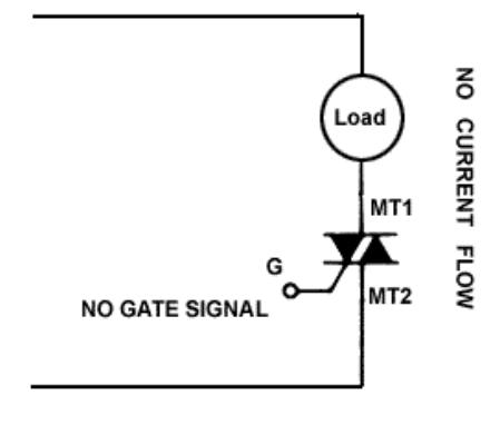
Figure 1
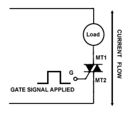
Figure 2
Due to its ability to conduct current in both directions, most PLC's that are used to control AC line powered devices utilize TRIACs in their solid state AC switch outputs. To further understand why there is leakage current a brief overview of triac theory is useful.
TRIAC Theory :
The TRIAC is a three terminal AC semiconductor switch, which is triggered into conduction when a low-energy signal is applied to its gate. Unlike the silicon-controlled rectifier (SCR), the triac will conduct current in either direction when turned on (reference figure 2). The triac also differs from the SCR in that either a positive or negative gate signal will trigger the triac into conduction. The triac may be thought of as two complementary SCR's in parallel.
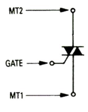
Figure 3
The triac offers a versatile method of accurately controlling AC power and has several advantages over conventional mechanical switches. Since the triac has a positive "on" and zero current "off" characteristic, it does not suffer from the contact bounce or arcing inherent in mechanical switches. The switching action is very fast compared to relays or mechanical switches, which gives more accurate control. DC, AC, rectified AC, or pulses can trigger a triac. Because of the low energy required to trigger a triac the control circuit can use lowcost solid state devices in its design.
Since a triac is a bilateral device the terms anode and cathode used for unidirectional devices have no meaning. Therefore, the terminals are simply designated MT1 and MT2 for the current carrying terminals and G for the gate terminal used to trigger the device (reference figure 3). To avoid confusion it is common practice to reference all currents and voltages using the MT1 terminal as the reference point.
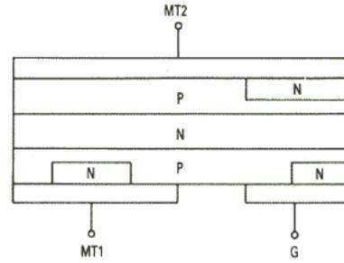
Figure 4
The basic structure of a triac is shown in figure 4 and shows why the symbol adopted for a triac consists of two complementary SCRs with a common gate. The triac is a five-layer device with the region between MT1 and MT2 being a P-N-P-N switch in parallel with a N-P-N-P switch. This structure allows the triac to be triggered by either a positive or negative gate signal.
The voltage-current characteristics of the triac are shown in figure 5. As was stated before, the MT1 terminal is used as a reference point. The first quadrant, Q-I, is the region where MT2 is positive with respect to MT1 and quadrant QIII is the opposite case. Several of the terms used in characterizing the triac are shown in the figure. For the purpose of this discussion we will concern ourselves to VDRM, IDRM and IH. VDRM is the break-over voltage of the device and is the highest voltage that the triac may be allowed to block in either direction. IDRM is the leakage current of the device with VDRM applied from MT1 to MT2, and is several orders of magnitude smaller than the "on" current rating of the triac. IH is the holding current, or the minimum value required to maintain conduction. When the current flowing through MT1 and MT2 drops below the IH value, the triac ceases to conduct and reverts to the blocking state.
Figure 5 shows the characteristics of the triac without a gate signal applied, but it should be noted that the device can be triggered into the "on" state at any value of voltage up to VDRM by the application of a gate signal. This is an important characteristic of the triac and makes it extremely useful for AC power control.
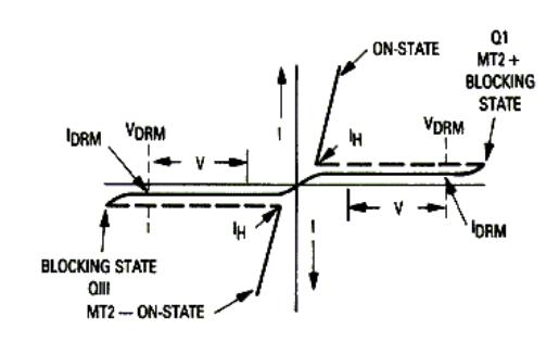
Figure 5
An important fact to remember is that since a triac can conduct current in both directions, it has only a brief interval during which the sine wave is passing through zero to recover it's blocking state. For this reason, reliable operation is limited to 60 Hz, or lower, line frequency signals.
TRIACs and Inductive loads :
A triac turns off every half-cycle when the current passes through zero. This is an important concept since when used to control an inductive load such as a motor or solenoid, the voltage and current waveforms do not coincide and often lag.
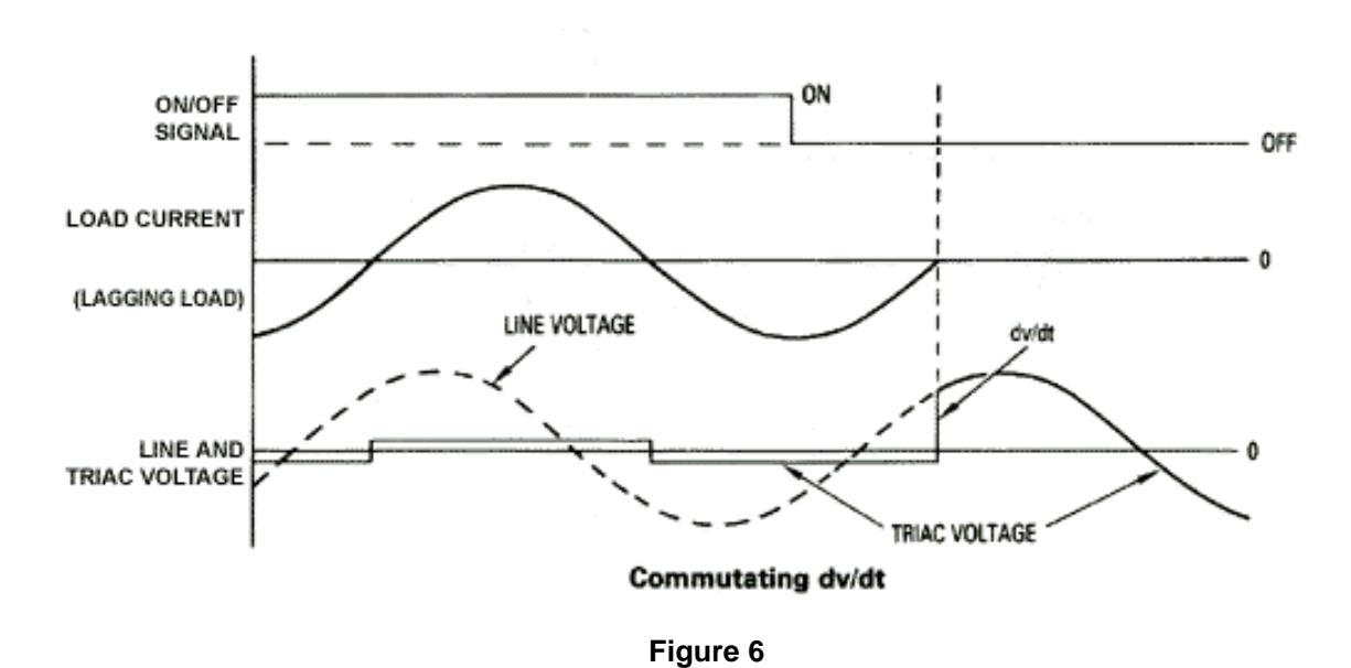
For inductive loads, the phase-shift between the voltage and current means that at the time the current falls below the IH value (holding current) and the triac ceases to conduct, there exists a certain voltage across the triac (reference figure 6). If this voltage appears too rapidly, the triac will resume conduction and control will be lost.
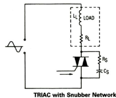
In order to achieve control with inductive loads, the rate of rise in voltage (designated as dv/dt) must be limited by a series RC (resistor/capacitor) network across the MT1 and MT2 terminals on the triac. The capacitor of this snubber circuit (RC network) will limit the dv/dt across the TRIAC. The resistor will prevent the surge of current from the capacitor when the triac turns on, and will dampen the ringing of the capacitance caused by the load inductance.
Snubbing Components:
Since triacs are most often used to control inductive devices they must be protected by the use of snubbing components. Figure 6 indicates what happens with an
inductive or lagging load. As in most applications, the on signal is removed asynchronously. The triac stays latched until the next current zero point. Since the current is lagging the applied voltage, the line voltage, at the instant of zero current, appears across the MT1 and MT2 terminals of the triac. It is the rate-of-rise of the voltage, what is called the commutating dv/dt, which must be limited in triac circuits. The dv/dt is usually limited to a few volts per microsecond. Anything higher and the triac will continue to conduct or if high enough, be destroyed.
To prevent the dv/dt from becoming too high, a snubber network is added to the triac circuit as shown in figure 7. The Rs and Cs values are chosen according to the current requirements and power factor of the load expected to be controlled. There are detailed formulas for determining the exact values of the components, but their selection is not pertinent for the purposes of this discussion. The most common values selected are 0.1uf for Cs and 100 ohms for Rs.
Leakage Current:
Figure 7
Referring back to figure 5, you can see that the IDRM, or leakage current, only reaches zero when the AC signal current waveform crosses zero. This leakage current is always present in thyristor devices and although it is several orders of magnitude smaller than the rated current of the device it can, for high current devices, be as much as 30ma. The snubber circuit that is utilized to clamp the commutating dv/dt also contributes to the leakage current. It is not uncommon for there to be an average of 10ma to 20ma of leakage current on a standard PLC output, since the PLC is typically designed to control devices drawing 20 to 30 amps.
The net result is that, in actuality, a solid state AC switching device is never completely "off". This condition is not a problem for industrial products that require many amps of current before they operate however, the 90 series strobes (excluding the 92PLC) are susceptible to this leakage current and, as a result, may spontaneously flash.
Bibliography
McMurray, William. "Optimum Snubber For Power Semiconductors," IEEE Transactions On Industry Applications , Vol. IA-8, September/October 1972
Blicher, Adolph. Tyristor Physics . Springer-Verlag, 1976.
Motorola Inc. "Motorola Thyistor Data," Banta Company 1993