Edwards Signaling 910 Installation Instructions
Open the original PDF document
View PDFP/N P-047550-0725 ISSUE 5

Instructions for Edwards Phone Page® Catalog Number 910
- - For use with telephones having modular (RJ11C type) jacks. For hard wired telephones or key systems (multiple line phones), use Edwards Cat. No. 913 Hard Wire to Modular Plug Adapter (ordered separately) in conjunction with the Phone Page and follow the installation instructions supplied with the adapter.
- - For connection only to a single line telephone or a key system. Not intended for use on "party line" phone service or on coin telephone lines.
- - For connection to telephone networks using standard plugs and telephone company supplied jacks or equivalent. When installed according to these installation instructions, the Phone Page can be readily disconnected without affecting equipment remaining on the telephone network.
- -For indoor installation only.
- - Registered with the Federal Communications Commission (FCC) in compliance with Part 68 of FCC Rules and Regulations
- -UL Listed Type NM (Non-Monitored) Signal Device
CHESHIRE, CT 203-699-3300 FAX 203-699-3365 (CUST. SERV.) FAX 203-699-3078 (TECH SERV.) © 2001
Make sure you read and thoroughly understand all instructions before installing this device.
Description
Edwards Cat. No. 910 Phone Page interfaces with an existing modular jack or hardwire telephone to provide for actuation of a supplementary signaling device during the telephone ring cycle. The signal turns off when either the telephone is answered or the call is unanswered and terminated by the calling party.
The Phone Page (see Figure 1) plugs into a standard 120V AC wall outlet and draws power to operate the signal directly from the power line. A ground type female receptacle is provided on the Phone Page for connection of the signaling device. Most any audible or visual signaling device that operates on 120V AC may be used.
The Modular Duplex Plug Adapter (Figure 1) supplied with the Phone Page allows for easy connection of the actuator to the telephone line. A separate modular telephone extension cord with a modular plug on each end is required for this connection. The required length of the cord will depend on your particular installation requirements. A 15-foot modular extension cord, Edwards Cat. No. 914, also is available from your supplier.
IMPORTANT TELEPHONE INFORMATION
Be sure you can provide the following information to the telephone company if it is requested:
Phone Number
FCC Registration Number: GYX30D-19623-RG-N
Ringer Equivalence Number: 1.0A/1.7B
The Ringer Equivalence Number (REN) allows you to determine the number of devices you can add to your telephone line and still have all the devices ring when your telephone number is called.
In most, but not all areas, the sum of all RENs for all devices connected to one line should not exceed 5.0. To be sure of the number of devices you can connect to your line, contact your local telephone company.
If the Phone Page damages the telephone network, the telephone company will notify you that it may temporarily disconnect your service if they feel such action is necessary. If you feel the disconnection is unwarranted, you have the right to bring a complaint to the FCC.
The telephone company may make changes in its communications facilities, equipment, operations, or procedures when such action is required. If these changes render the Phone Page incompatible with the telephone company facilities, the telephone company will provide enough written notice so that you can make the necessary changes to maintain uninterrupted service.
Installation
- 1. There are three possible locations for installation of the Modular Duplex Plug Adapter as shown in Figure 2. The Duplex Adapter can be installed on the telephone junction box (Example 1), on the Phone Page (Example 2), or on the telephone (Example 3). Determine which method best suits your installation requirements and install the Duplex Adapter.
- 2. Plug one end of a separate modular telephone extension cord (not supplied) into a receptacle in the Duplex Adapter. Then plug the other end of the cord into the jack in either the bottom of the Phone Page (Ex. 1 or 3) or into the jack in the telephone junction box (Ex. 2).
- 3. The Phone Page must be installed on a 120V AC ground type duplex wall outlet. This outlet should be located close to the are where the signaling device is to be located so that the device can be directly connected to the Phone Page without the use of an extension cord. If a ground type outlet is not available or is not located such that direct connection of the signal is possible, you should contact a licensed electrician to have a new outlet installed. A screw is provided with the Phone Page for securing the unit to the outlet.
WARNING
Removal of the faceplate from the wall outlet is not required and should not be attempted as this would present a risk of electrical shock.
- a. Remove the screw from the center of the wall outlet faceplate. DO NOT REMOVE THE FACEPLATE.
- b. Plug the Phone Page into the lower receptacle of the duplex outlet.
- c. Secure the Phone Page to the outlet by installing the screw supplied with the Phone Page through the hole in the top of the Phone Page's backplate and into the screw hole in the center of the faceplate.
- 4. The signaling device to be connected to the Phone Page must be rated for 120V AC operation. The signal load must not exceed 10 amps resistive (300 Watts tungsten) or 4 amps inductive. When more than one signaling device is to be used, connect all devices in parallel. Typical devices that may be used include Edwards horns, bells, and flashing lights, and other electronic signaling devices, as well as household type lamps. Refer to the separate sheet supplied with the Phone Page for a list of recommended Edwards signaling devices.
- 5. Plug the power cord from the signaling device directly into the 120V outlet on the front of the Phone Page as shown in Figure 3. The use of extension cords and plug-in type outlet adapters to connect the device to the Phone Page is not recommended. If the signaling device includes a power switch, turn the switch to the ON position so that the device will operate when the telephone rings.
Maintenance and Repair
If the Phone Page should fail to operate properly, disconnect it from the telephone line and see if the problem is due to the telephone line or the Phone Page.
CAUTION Do not disassemble this device. It does not contain any servicable components.
If the problem is in the Phone Page, remove it from service and return it to your local Edwards distributor. Contact our customer service department at (203) 699-3367 for a distributor in your area.
Specifications
| Nominal Input Voltage | |
|---|---|
| Input Voltage Limits | 102-132V 50/60 Hz |
| Maximum Output Load10 Amps | Resistive, 4 Amps Inductive, 300W Tungsten |
| Power Requirement (not including signaling device load) | |
| Standby | |
| On | 0.67 Watts at 90V |
| Ring Signal Voltage Limits | 90V AC + 30% @ 20 Hz @ 0.33 Duty Factor |
| Input Characteristics | |
| Tip to Ring Impedance | |
| DC Resistance | Infinite |
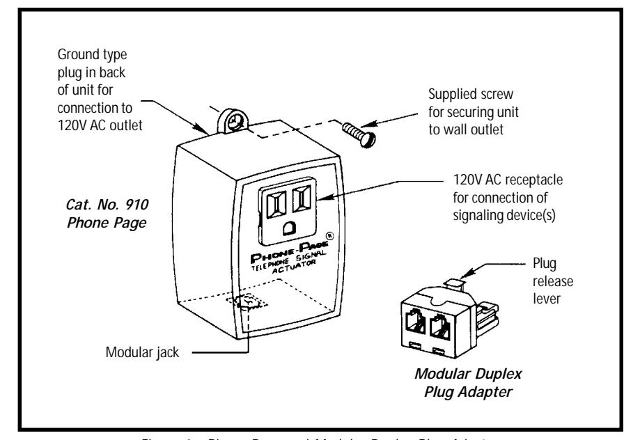
Figure 1. Phone Page and Modular Duplex Plug Adapter
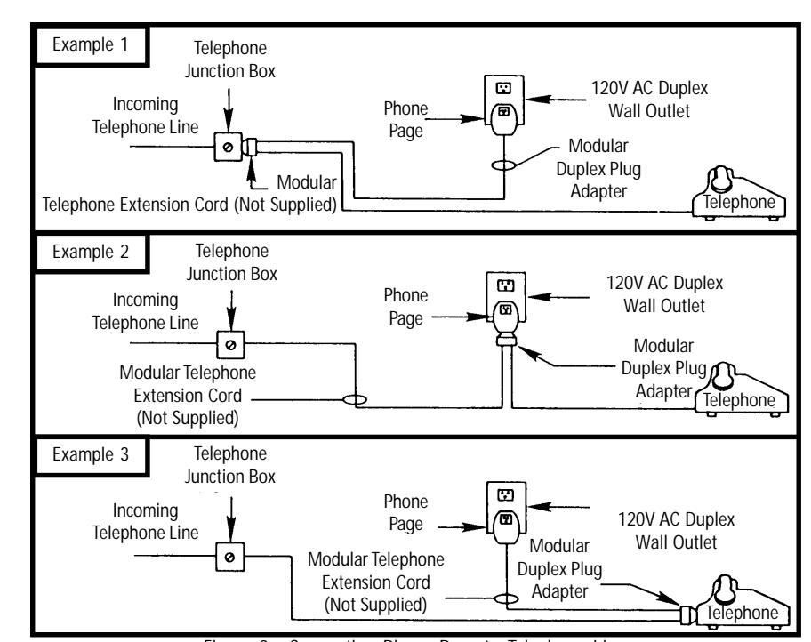
Figure 2. Connecting Phone Page to Telephone Line
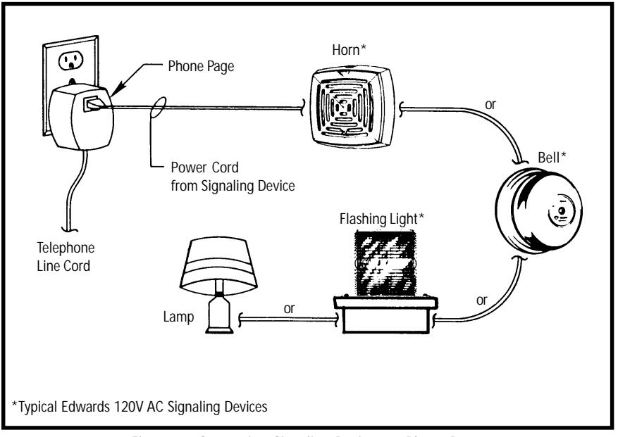
Figure 3. Connecting Signaling Devices to Phone Page