Edwards Signaling 870 Series Indoor – Installation Instructions
Open the original PDF document
View PDF

Installation Instructions for Indoor AdaptaHorns
Description
The AdaptaHorns are UL listed vibrating horns. They are low current, high decibel horns designed for heavy-duty use indoors. The horns are intended for general signaling applications.
PLC Compatibility
The electrical input load requirements for PLC compatible signaling devices are listed in Table 1. Signaling devices may be directly connected to output cards that meet these input load requirements.
24V DC electromechanical horns such as the 871-G1, 873-G1, 873DPO-G1 and 875-G1 can produce transient spikes and should only be used on PLC output cards that have inherent transient spike suppression. The Process Control Engineer should consult the PLC manufacturer when connecting 24V DC electromechanical devices to PLCs.
Installation
Flush Mounting (870 and 871 Series)
Using approved wiring methods, connect black wire leads to power source wires. Polarity is not important.
- 2. Ground to wiring system.
- 3. Insert horn connector into connector receptacle and secure horn to backbox with (4) oval head screws (supplied).
Surface Mounting (872, 872DPO, 873, 873DPO, 874, and 875 Series)
- 1. Loosen screw at bottom of horn and remove backplate.
-
2. Mount plate using one of the following methods:
- a. Mount on any outlet box cover having single gang opening using #6 screws (supplied).
- b. Mount on a 3 1/4" (83mm), 3 1/2" (89mm), 4" (102mm) octagon or 4" (102mm) square box using #8 screws supplied with backbox.
- c. Mount on the wall, for open wiring, using #8 wood screws (supplied).
- 3. Using approved wiring methods connect one wire to each terminal in backplate. Ground to wiring system.
- 4. Place the horn on the mounting plate so that the tab at the top seats in slot on horn. Press horn firmly against plate and tighten screw at bottom of unit. See Figure 1.
| Cat. No. | Operating voltage* | Maximum off state leakage current (mA) | Continuous on current (mA) |
Surge (inrush/duration)
(A/ms**) |
|---|---|---|---|---|
| 870-N5 | 120V AC | 25 | 120 | 1.02/0.000026 |
| 871-G1 | 24V DC | 25 | 150 | 1.7/0.000042 |
| 872-N5 | 120V AC | 25 | 120 | 1.02/0.000026 |
| 872DPO-N5 | 120V AC | 25 | 120 | 1.02/0.000026 |
| 873-G1 | 24V DC | 25 | 150 | 1.7/0.000042 |
| 873DPO-G1 | 24V DC | 25 | 150 | 1.7/0.000042 |
| 874-N5 | 120V AC | 25 | 120 | 1.02/0.000026 |
| 875-G1 | 24V DC | 25 | 150 | 1.7/0.000042 |
* All AC volts at 60 Hz
** Amps/milliseconds
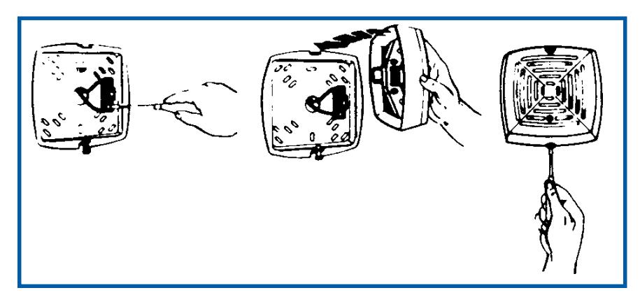
Figure 1. Mounting the Horn on the AdaptaPlate
Volume Adjustment
These devices have a volume adjustment screw (located on the grille front) factory set to maximum. To reduce volume level, turn set screw clockwise using the supplied 1/16" (1.6mm) allen wrench.
Table 2. Electrical Specifications
| Cat. No. | Voltage | Current |
|---|---|---|
| 870-G5 | 24V 50/60 Hz | 0.63A |
| 870-N5 | 120V 50/60 Hz | 0.13A |
| 870-R5 | 240V 50/60 Hz | 0.07A |
| 871-E1 | 12V DC | 0.27A |
| 871-G1 | 24V DC | 0.16A |
| 871-K1 | 48V DC | 0.07A |
| 871-P1 | 125V DC | 0.025A |
| 871-S1 | 250V DC | 0.014A |
| 872-E5 | 12V 50/60 Hz | 1.25A |
| 872-G5 | 24V 50/60 Hz | 0.63A |
| 872-N5 | 120V 50/60 Hz | 0.13A |
| 872-R5 | 240V 50/60 Hz | 0.07A |
| 872DPO-G5 | 24V 50/60 Hz | 0.63A |
| 872DPO-N5 | 120V 50/60 Hz | 0.13A |
| 872DPO-R5 | 240V 50/60 Hz | 0.07A |
| 873-G1 | 24V DC | 0.16A |
| 873-K1 | 48V DC | 0.07A |
| 873-P1 | 125V DC | 0.025A |
| 873-S1 | 250V DC | 0.014A |
| 873DPO-E1 | 12V DC | 0.27A |
| 873DPO-G1 | 24V DC | 0.16A |
| 873DPO-J1 | 32V DC | 0.13A |
| 873DPO-P1 | 125V DC | 0.025A |
| 873DPO-S1 | 250V DC | 0.014A |
| 874-E5 | 12V 50/60 Hz | 1.25A |
| 874-G5 | 24V 50/60 Hz | 0.63A |
| 874-N5 | 120V 50/60 Hz | 0.13A |
| 874-R5 | 240V 50/60 Hz | 0.07A |
| 875-C1 | 6V DC | 0.70A |
| 875-E1 | 12V DC | 0.27A |
| 875-G1 | 24V DC | 0.16A |
| 875-J1 | 32V DC | 0.13A |
| 875-P1 | 125V DC | 0.025A |
| 875-S1 | 250V DC | 0.014A |