Edwards Signaling 869D-G1 Installation Instructions
Open the original PDF document
View PDF

Installation Instructions for 869D-G1 Series Diode Polarized Electronic Horn Signal Appliance
Description
The horns are UL and cUL Listed, high quality signals intended for indoor or outdoor use. It is recommended that these products be installed in accordance with the requirements in the latest edition of national and local electrical codes. For outdoor use, the horns must be installed with a weatherproof backbox.
It is recommended that these products be installed in accordance with the requirements in the latest edition of national and local electrical codes.
See Table 2 and Figure 1 for specifications.
Table 1. Electronic Horns
| Description |
Catalog
Number |
|---|---|
| Horn, Gray, Flush or Panel Mount, Indoor Indoor | 869D-G1 |
Installation
A
WARNING
To reduce the risk of shock, always disconnect all power before handling the unit.
-
Select mounting method as detailed in Figure 1 and install the electrical box (not supplied) using suitable hardware.
- a. For outdoor applications, install the weatherproof box (ordered separately) using four #10 x 1 1/4" (32 mm) screws and cap lugs provided in the enclosed parts bag.
NOTE: Be sure hook flange is facing outward as shown in Figure 1.
NOTE: The designation "TOP" on boxes denotes orientation of box after installation.
- 2. Attach mounting plate using two #8-32 screws provided with the surface box (ordered separately) or four #8-32 screws provided with the weatherproof box (ordered separately). The flush box uses two #8-32 screws (not provided).
- 3. Bring signaling circuit field wiring into electrical box.
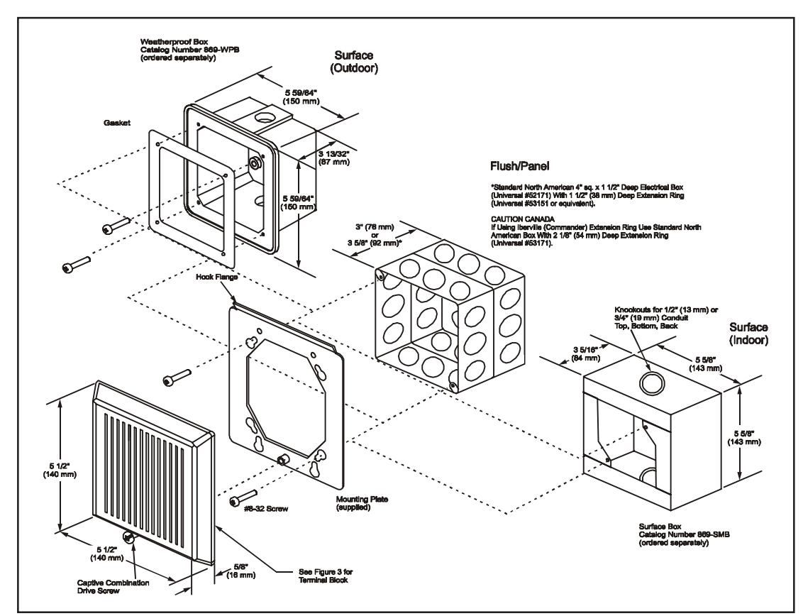
Figure 1. Detailed View
- 4. Ground in accordance with national and local electrical codes. A green ground screw is provided with both the indoor and outdoor surface boxes.
- 5. Connect signaling circuit field wires to terminals on horn assembly (Figures 2 and 3).
-
6. Mount the horn assembly on the mounting plate (Figure 1).
- a. The inside of the top of the grille has hinges that pass through cutouts and engage with tabs on the mounting plate. With the bottom of the grille lifted out slightly, place the grille over the mounting plate so that the hinges of the grille are in the mounting cutouts.
- b. Properly seat the grille by pressing the bottom in.
- Fasten the bottom of the grille to the mounting plate by installing the captive combination drive screw.
- 7. Apply power and activate the horn/strobe unit to verify that it is operating properly.
Maintenance

CAUTION
Should the unit fail to operate properly, do not attempt repair. Contact the supplier for replacement.
Perform a visual inspection and an operational test twice a year.
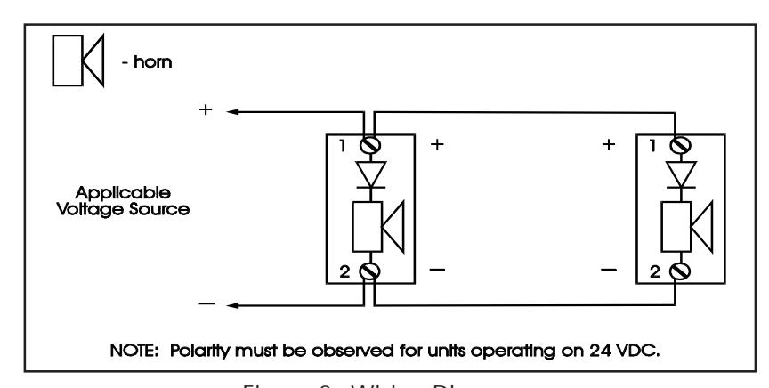
Figure 2. Wiring Diagrams

Figure 3. Terminal Block
Table 2. Specifications
| Operating Voltage | 24V DC |
|---|---|
| Operating Current - Horn* |
20 mA (low volume) @ 20 to 24V DC
40 mA (high volume) @ 20 to 24V DC |
|
Sound Level Output at 10 ft. (3.05 m)
Anechoic Chamber |
98 dBA peak (low volume)
102 dBA peak (high volume) |
| Operating Environment Indoor | 93% relative humidity @ 104F (40C); 32 to 120F (0 to 49C) variable ambient temperature |
| Outdoor | 98% relative humidity @ 104F (40C); -31 to 150F (-35 to 66C) variable ambient temperature |
* The operating voltage to the horn may be continuous or coded such as march time or a temporal pattern meeting ISO8201 (ANSI S3.41) Audible Emergency Evacuation Signal.
Contacting Edwards:
Phone: (203) 699-3000
E-Mail: techsupport@edwards-signals.com
customerservice@edwards-signals.com
Website: http://www.edwards-signals.com
P/N 3100286 ISSUE 2 PAGE 2