Edwards Signaling 700 Series Installation Instruction
Open the original PDF document
View PDF

ESL 700 Series Conventional Smoke and Heat Detector Installation Sheet
Description
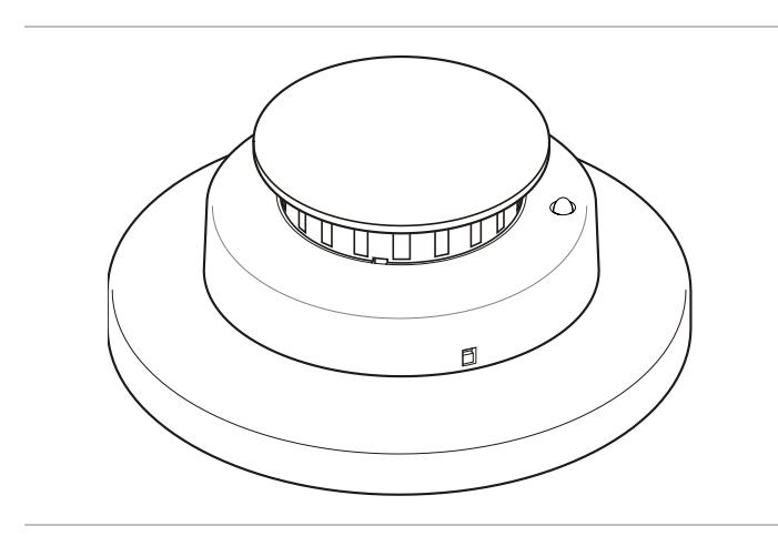
The ESL 700 Series smoke or smoke with rate-of-rise heat detectors have field-replaceable optical chambers. The detector uses an optical sensing chamber to detect smoke and a fixed-temperature heat sensor to detect heat from fire. For a list of model numbers, see Table 1. For a list of accessories, see Table 2.
Table 1: Model numbers
| Number | Description | |
|---|---|---|
| Head (sold separately from base) | ||
| 711U | Two-wire photoelectric smoke detector head | |
| 713-5U |
Two-wire rate-of-rise and 57°C (135°F) fixed
temperature heat detector head |
|
| 721U |
Two-wire photoelectric smoke detector, with remote test
input and remote alarm/trouble LED output |
|
| 721UT |
Two-wire photoelectric, with rate-of-rise heat detector
head with remote test, alarm/trouble LED output |
|
| 731U [1] |
Two-wire photoelectric smoke detector head with
auxiliary relay (NC/NO) output |
|
| 741U |
Four-wire photoelectric smoke detector with alarm relay
(NO) output and remote alarm/trouble LED output |
|
| 741UT |
Four-wire photoelectric smoke and rate-of-rise heat
detector head, alarm relay (NO) output and remote alarm/trouble LED output |
|
| 731L | (OEM only, not for resale) see 731U description | |
| Base (sold separately from head) | ||
| 701U |
Three-terminal base for 711U and 713-5U heads, 6 in.
(15 cm) base, connectors |
|
| Number | Description | |
|---|---|---|
|
702E
10PKG |
Six-terminal base for all heads; 4 in. (10 cm) | |
| 702U | Six-terminal base for all heads, 6 in. (15 cm) | |
| 702RE | Six-terminal base for 731U, 4 in. (10 cm) | |
| 702RU | Six-terminal base for 731U, 6 in. (15 cm) | |
| Head with base (sold together) | ||
| TS7-4 |
Four-wire photoelectric smoke detector with alarm relay
(NO) output and remote alarm/trouble LED output |
|
[1] UL Listed for releasing devices such as electromagnetic door holders, fire dampers, or smoke dampers.
High voltage (120 V) base and head
The 702RE and 702RU bases have a special plastic protrusion built in to prevent insertion of a low-voltage detector head into a base containing damaging high voltages (120 V). These bases can only be used with 731U heads. The 731U includes auxiliary relay contacts and is only required when connecting high voltage to the auxiliary relay.
Note: The 731U heads can also be used with 702E and 702U bases for low voltage applications.
Table 2: Accessories
| Description |
|---|
|
End-of-line, power supervision relay for four-wire
applications |
|
Replaceable optical chamber for ESL smoke
detectors (set of 10) |
|
Remote indicator with red alarm LED, for use with
721U and 741UT |
|
Remote indicator with red alarm LED and keyed
remote test, for use with 721U and 721UT |
|
Remote indicator with red alarm LED, keyed
remote test and reset, for use with 721U and 741UT |
|
Smoke! In A Can (canned smoke) for functional
testing of smoke detectors |
| Extension tube for Smoke! In A Can |
[1] The remote alarm/trouble LED on the 706U1A, 706U2A, and 706U3A models works with both two-wire 721U/721UT and four-wire 741U/741UT models when connected as shown in Figure 6 item 7 and Figure 7 item 11.
[2] 706U2A and 706U3A only work with the 721U/721UT two-wire models, when connected as shown in Figure 6 item 6.
Installation
Notes
- Locate detectors in an operating environment as defined in "Specifications" on page 6.
- Mount detectors on a firm, permanent surface.
Placement and spacing
Use the following location guidelines to optimize performance and reduce the chance of false alarms.
Smoke detectors:
- Locate wall-mounted smoke detectors so the top of the detector is no lower than 12 in. (30 cm) below the ceiling. See Figure 1.
- As a guide, space smoke detectors on smooth ceilings 30 ft. (9.1 m) apart. When determining other spacing, consider ceiling height, high air movement, and other conditions or response requirements. Refer to NPFA 72.
- Locate detectors away from air conditioners, heating registers, and any other ventilation source that may interfere with smoke entering the unit; also away from kitchens, wood stoves, garages, furnaces, and bathrooms.
Heat detectors:
- Do not install heat detectors in areas with an ambient temperature above 100°F (38°C).
- Mount heat detectors on the ceiling no closer than 4 in. from the sidewall. On the wall, mount them between 4 and 12 in. from the ceiling.
- When determining detector placement, consider ceiling height, construction, and ventilation as these affect a detector's performance. Refer to NPFA 72.
Installing the base
Select a compatible electrical box for the base. See "Specifications" on page 6 for a list of compatible electrical boxes.
The 6-inch diameter bases have three parts; the base itself that mounts on the electrical box or ceiling, a foam gasket, and the base cover that conceals the mounting screws (see Table 1 for model numbers and descriptions). The 6-inch diameter bases are shipped loosely coupled to the base cover.
Figure 1: Smoke detector placement
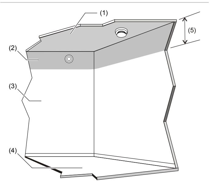
- (1) Smooth ceiling
- (2) Gray indicates the acceptable mounting area
- (3) Wall
- (4) Floor
- (5) 12 in. (300 mm) max.
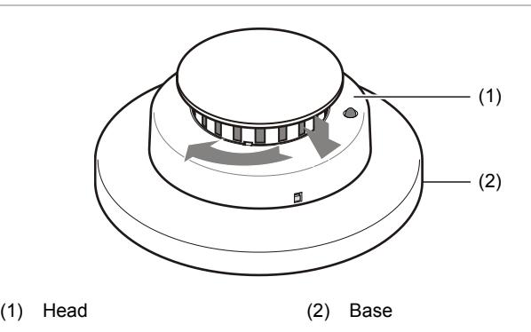
Figure 2: The six-inch diameter mounting base
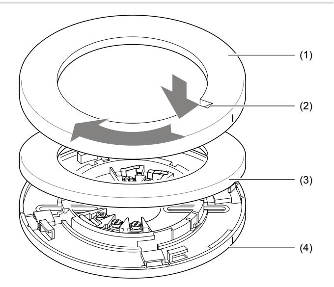
- (1) Base cover
- (2) Screwdriver slot to unlock the head
- (3) Gasket
- (4) Base
To install the base:
- 1. Remove the base cover by simply twisting it counterclockwise to unsnap (see Figure 2).
- 2. Pull the field wires through the electrical box, and then through the center opening of the base. Connect the wires to the appropriate terminals according to the wiring diagrams (see Figure 6 or Figure 7).
- 3. Dress the wiring neatly, and then verify that the continuity switch (jumper wire) is touching both terminal 1 and terminal 2 (see Figure 8). Securely fasten the base with the appropriate hardware.
- 4. Check all wiring and mounting connections.
- 5. Install the gasket. Align the molded line on the base with the base cover, and then twist clockwise to snap in place.
Consider the locking mechanism before installation
Each detector head is equipped with a breakaway locking tab to prevent unauthorized removal of the detector head (see Figure 3). For installations where unauthorized removal of the detector head is not a concern, the head removes by simply turning counterclockwise.
However, when the head must lock to the base, break away the locking tab with a pair of pliers. Then, to remove the detector head, insert a small screwdriver into the slot on the side of the base, pressing in while simultaneously turning the detector head counterclockwise (see Figure 5).
Figure 3: Removing the locking tab slot
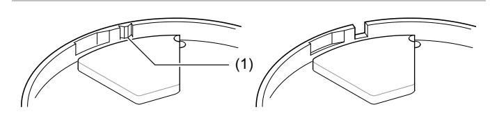
(1) To lock, break out this tab with pliers
Installing the detector head
To install a detector head, insert the head and rotate it clockwise to properly align and seat it into the base (see Figure 4). Then rotate it an additional 15 degrees to lock it in place. This action automatically opens the continuity switch in the base and establishes continuity in the system.
Figure 4: Installing the detector head
Removing the detector head
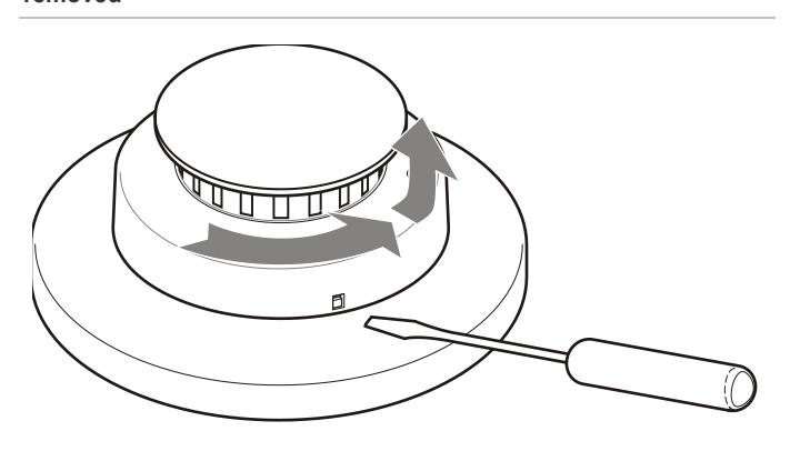
To remove the detector head, turn it counterclockwise. If the locking tab was removed, insert a small screwdriver into the locking tab slot on the side of the base, and then press in while simultaneously turning the detector head counterclockwise (see Figure 5).
Figure 5: Removing the detector head with the locking tab removed
Wiring
Caution: Risk of system failure. The system may not operate if the detector is not connected to the control unit initiating device circuit as specified in the detector or control unit literature.
For two-wire installation, see Figure 6.
For four-wire installation, see Figure 7.
For optional four-wire operation, verify that the voltage range of the control panel power supply is within the detector voltage range, and that sufficient current is available to ensure the operation of all detectors.
End-of-line supervision for four-wire systems
NFPA 72 requires supervision of power wiring in four-wire systems. To accomplish this, install a power supervision unit for the appropriate control unit voltage at the end of the detector power circuit. See Figure 7.
The model 204-12/24V power supervision relay accommodates both 12 VDC and 24 VDC operation. See the 204-12/24 V installation sheet for more information.
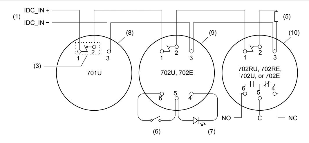
Figure 7: 700 series four-wire wiring diagram (741UT head)
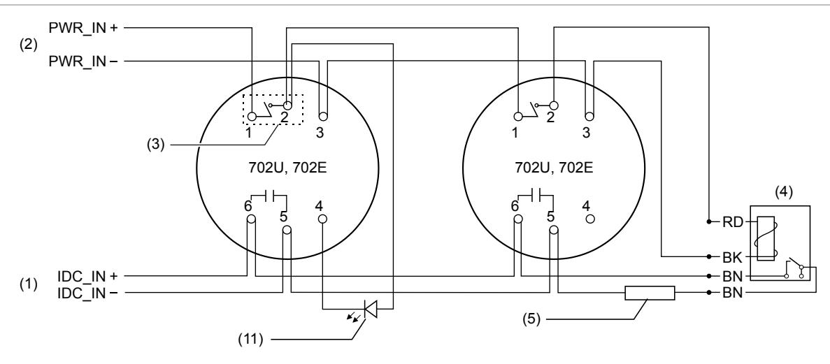
- (1) Initiating device circuit from a compatible listed control panel
- (2) DC power circuit
- (3) Continuity switch
- (4) Power supervision relay (P/N 204-12/24V)
- (5) End-of-line device
- (6) Remote test switch P/N 706U2A (for 721U and 721UT detectors only in this two-wire application)
Note: Alarm contacts are shown in the normal state.
Testing
- Prior to testing, remove the red dust cover. The units do not work with the dust cover in place.
- Follow the control panel's recommended test procedure. To limit inconvenience to building occupants during testing it may be necessary to disable or disconnect the alarm notification appliances, HVAC shutdown, elevator control, releasing service devices, and extinguishing systems prior to detector tests. If these or other functions controlled by the fire system are disconnected during testing, be sure to perform other tests to confirm that these functions will operate during an actual event.
- Be sure to enable or reconnect all devices at the conclusion of testing.
- (7) Remote LED P/Ns 706U1A, 706U2A ,or 706U3A (for 721U or 721UT detector only)
- (8) Base for 711 series and 713-5U detectors
- (9) Base for 721UT detector only
- (10) Base for 731U series detectors
- (11) Remote LED P/Ns 706U1A, 706U2A, or 706U3A (for 741U or 741UT detectors only)
Testing the wiring for continuity
After all universal mounting bases are installed, including the end-of-line device, check the system wiring for continuity. Verify that the manually operated continuity switch in each base is in the shorting position — making contact with terminals 1 and 2 (for use at initial installation only). See Figure 8. Use a screwdriver to reset any unshorted continuity switches (reset by prying the jumper wire out of the plastic stopper). This establishes continuity across the alarm initiating circuit at initial installation. The wiring can now be tested for continuity using an ohmmeter or "megger."
Figure 8: Continuity switch
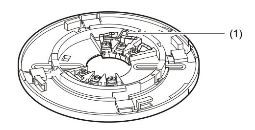
(1) Continuity switch
Testing the system
After completing all the connections and checking the wiring per NFPA 72, apply power to the system. There should be no alarm. If there is an alarm, check each detector to see if the alarm LED is active. Reset the control panel and see if the alarm clears. If the alarm does not clear after the panel is reset, power down the system and determine if there is a problem with the wiring. If there is no alarm, go to the last unit and use a voltmeter to check the unit power for the specified voltage.
Testing the smoke detector
Test the units in place annually, using Smoke! In A Can and following the directions on the can.
The unit performs a smoke test every 9 seconds while flashing its LED. If smoke is detected, the rate of sampling increases to every 4.5 seconds. The smoke detector must detect excessive smoke in three consecutive tests for the alarm to sound.
If the test is successful (alarm sounds), the LED stays on. This is a gross, go/no-go test and is not a reliable indication of unit sensitivity. For in-depth sensitivity testing, see "Performing a sensitivity test on a smoke detector" below.
To reset the detector, follow the control panel's reset procedure. Resetting the control panel will remove power from the detector and allow it to reset. For a complete test of each detector, verify the control unit alarm and all ancillary functions.
Performing a sensitivity test on a smoke detector
1. Hold a test magnet near the raised TEST letters on the detector for more than one second (see Figure 9).
The LED flashes 1 to 9 times.
2. Count the number of LED flashes, and then use Table 3 to determine the required action.
Table 3: Description of LED flashes
| 0 to 1 | Indication: Unserviceable hardware fault. |
|---|---|
|
Action: Reset and rerun the sensitivity test. If the error
persists, replace the unit. |
|
| 2 to 3 | Indication: Unit is becoming insensitive. |
|
Action: Clean and reset the unit. Rerun the sensitivity test. If
the error persists, replace the unit. |
|
| 4 to 7 | Indication: Unit is within normal sensitivity range. |
| Action: None | |
| 8 to 9 | Indication: Unit is becoming too sensitive. |
|
Action: Verify that the optical chamber is snapped down
securely. If the chamber is correctly installed, clean the unit and replace the optical chamber. |
After the sequence of flashes, if the detector finds the sensitivity to be within limits and if all other tests pass, the detector goes into alarm until reset by the panel. If the sensitivity is not within limits, or an unserviceable hardware fault is detected, the alarm LED continues to flash once per second until the detector is reset by the panel. If the sensitivity test indicates an unacceptable level, take the action recommended in Table 3. If this action does not result in acceptable sensitivity, replace the unit.
Figure 9: Smoke detector sensitivity level test
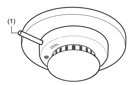
(1) Test magnet
Remote LED
Models 721U/721UT and 741U/741UT have connections for an optional remote LED. The remote LED flashes every 9 seconds for a normal state, flashes once every second for a trouble state, and turns on steady in alarm. It does not indicate during loss of power.
Testing the heat detector
The 713-5U heat detector samples for heat continuously. The photoelectric smoke/heat detectors sample for heat every three seconds.
To test the heat detector:
1. Aim a hot air gun at the detector from 6 to 10 in. (15 to 25 cm) away, taking care not to melt the plastic.
The detector should go into alarm in less than 30 seconds.
Maintenance
If a smoke detector drifts beyond its approved sensitivity range for more than 24 hours, or fails internal diagnostic tests during power-up, the unit automatically indicates trouble by flashing its LED every second. Under normal conditions, the LED flashes every nine seconds. Therefore, a visual check of the LED status meets NFPA 72 field sensitivity testing requirements.
In accordance with NFPA 72, visually check the LED flashes for unit sensitivity within one year of installation and every alternate year thereafter for commercial installations, or every three years for residential sites.
Cleaning the smoke detector
The smoke detectors have an optical chamber that unsnaps for easy field cleaning and service. Whenever the LED indicates that cleaning is necessary, follow the steps given below.
To clean the smoke detector:
- 1. Remove the detector cap (see Figure 10), and then unsnap and throw away the optical chamber.
-
2. Use compressed air to thoroughly clean the optical base, and then snap a new optical chamber into place.
- Note: Be sure the new optical chamber is seated all the way down.
- 3. Replace the detector cap and verify sensitivity. See "Performing a sensitivity test on a smoke detector" on page 5.
Figure 10: Optical chamber
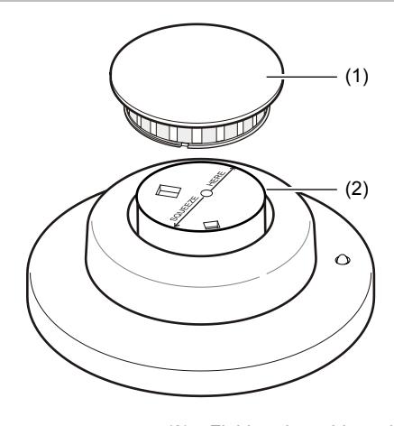
- (1) Detector cap (2) Field-replaceable optical chamber
Specifications
| Voltage | 8.5 to 33 VDC, not polarity sensitive |
|---|---|
| Maximum ripple | 10% (Vp-p) |
|
Typical average
standby current (24 V) |
711U, 713-5U: 70 μA
721U, 721UT, 731L, 731U, 741U, 741UT: 100 µA |
| Typical alarm current |
Two-wire: 60 mA (max.), if not limited by
control panel |
|---|---|
| Four-wire: 50 mA (max.) but 15 mA (min.) | |
|
Remote LED output
current |
5.0 to 8.5 mA |
| Relay contacts | 2 A at 30 VDC, 1 A at 120 VAC |
| RFI immunity | 20 V/m minimum, 0 to 1,000 MHz |
| Heat detector | Fixed temperature: 135° ±3°F (57° ±1.7°C) |
| specifications [1] |
Rate of rise: 15°F/min and > 105°F
(8.3°C/min and > 40.6°C) |
| Heat detector spacing | 721UT, 741UT: 50 ft. |
| 713-5U: 70 ft. | |
| Sensitivity | 1.55 to 3.22%/ft. obscuration |
|
Drift compensation
adjustment |
1.0%/ft. max. for photoelectric models |
| Remote test input | 100 Ω max. |
| Reset voltage | 2.5 V max. |
| Reset time | 1 second min. |
| Color | White head and base |
|
Detector head
dimensions |
4 in. (10 cm) diam., 1.75 in. (4.44 cm) height |
| Base dimensions |
701U, 702U, 702RU: 6 in. (15.2 cm) diam.,
0.6 in. (1.3 cm) height |
|
702E, 702RE: 4 in. (10 cm) diam., 0.5 in.
(1.27 cm) height |
|
|
Compatible electrical
boxes [2] |
701U, 702U, 702RU: Standard single-gang
electrical boxes; 4-inch square, round, or octagonal boxes; 3.5-inch octagonal boxes; WIREMOLD 5738A or 5739 fixture boxes |
| 702E, 702RE: 3-inch round electrical boxes | |
|
Total height, head and
base together |
1.98 in. (5 cm) |
| Field wiring size | 12 to 24 AWG |
|
Operating environment
Temperature Relative humidity |
32 to 100°F (0 to 38°C)
0 to 95% noncondensing |
[1] For models 713-5U, 721UT, and 741UT.
[2] Bases may also be mounted without electrical boxes if the AHJ approves it or if codes allow.
Regulatory information
| Listings | UL Listed (UL 268 and UL 521) |
|---|---|
| FM Approved (except for TS7-4 and TS7-4T) | |
| CSFM (California State Fire Marshal) Approved | |
| UL two-wire | S10A for all models except 731U/731L |
| compatibility | S11A for 731U/731L |
| identifier | S00 for all bases |
Contact information
For contact information, see www.interlogix.com.