Edwards Signaling 6538-G5 Installation Instructions
Open the original PDF document
View PDF

Installation Instructions for the 6538-G5 Call for Assistance Package
Description
The 6538-G5 Call for Assistance Package lets handicapped individuals alert the general area when they need emergency assistance. The Call for Assistance Package mounts outside and above the entrance of public rest room faiclities. It signals an audible and visual alarm when the cord switch is pulled from inside the facility. The kit contains a Pull Cord Switch (Cat. No. 6537), Horn/Strobe (Cat. No. 6536-G5), and Transformer (Cat. No. 592). Each item can be purchased separately. Contact your local Edwards distributor for more information.
Installation
A qualified electrician familiar with National Electrical Code and local code requirements must install this product. Failure to follow the safety precautions in this instruction sheet could result in product or property damage, severe personal injury or death.

WARNING
To reduce the risk of shock, do not connect AC power until installation is complete.
-
1. Install Cat. No. 6537 Pull Cord Switch (Figures 1 and 2).
- a. Install a single gang 2" x 4" (51 mm x 102 mm) electrical box using suitable hardware.
- b. Extend the black and white wires using 18 AWG wire and connectors (not supplied). Route the extended wires to the horn/strobe and transformer (polarity is not important). Ground in accordance with local codes and regulations.
- c. Mount the pull cord switch onto the electrical box using two screws (supplied).
- 2. Install Catalog No. 6536-G5 horn/strobe (Figures 1 and 4).

WARNING
To reduce the risk of shock, do not remove lens or tamper with unit when the circuit is energized. Disconnect power and allow five (5) minutes for stored energy to dissipate before starting work or disassembly. High energy could be stored in the strobe circuit once it is energized.
The 6536-G5 horn/strobe can be mounted on any single gang 2" x 4" (51 mm x 102 mm) electrical box, double gang 4" x 4"
(102 mm x 102 mm) electrical box, or standard 4" x 4" (102 mm x 102 mm) junction box with a plaster ring.
- Install an appropriate electrical box using suitable hardware.
- b. Connect one wire from the 6537 pull cord to one of the horn/strobe wires (polarity is not important).
- c. Extend the remaining horn/strobe wire to the transformer.
- d. Mount the horn/strobe onto the electrical box using two screws (supplied).
-
3. Install Catalog No. 592 Transformer (Figures 1 and 3).
- a. Select a metal electrical box that can be grounded. Mount the transformer onto the electrical box (Figure 3) so that it has ground continuity to the box and conduit system.
- b. Install the box using suitable hardware.
- Ground the box in accordance with local codes and regulations.
- d. Connect the remaining pull cord switch wire to one of the terminals marked 24V 20VA.
- e. Connect the horn/strobe wire to the second terminal marked 24V 20VA.
- f. Connect the transformer's primary wire leads to an appropriate 120V AC power source.
- 4. When all connections are completed, pull the cord switch and verify operability of the horn/strobe.
- 5. Reset the unit using the switch on the cover of the Cat. No. 6537 Pull Cord (Figure 2).
Maintenance
Perform regularly scheduled testing at least twice a year or more often as dictated by local authorities having jurisdiction.
The 6538-G5 Call for Assistance Package is not serviceable or repairable. Should it fail to operate properly, contact the supplier for replacement.
Table 1. Specifications
| Horn/Strobe Voltage | 24V 50/60 Hz | 24V DC | |
|---|---|---|---|
| norm/strobe voltage | 24 V 30/60 HZ | 24 V DC | |
| Horn/Strobe Current | 175 mA | 125 mA | |
| Transformer - | Primary | 120V | |
| - | Secondary | 24V 20VA | |
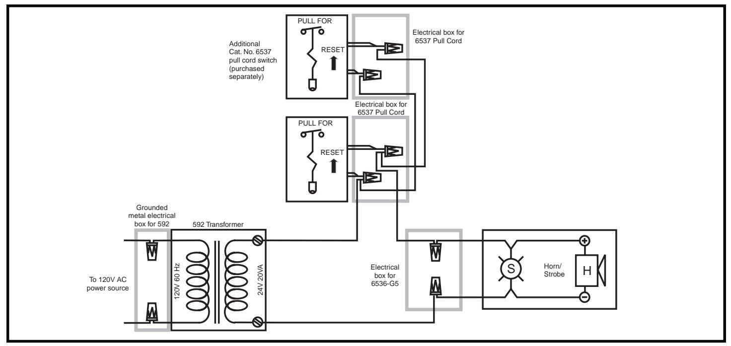
Figure 1. Connecing Catalog No. 6538-G5 Call for Assistance Package
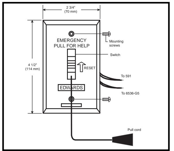
Figure 2. Catalog No. 6537 Pull Cord Switch
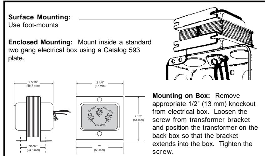
Figure 3. Catalog No. 592 Transformer
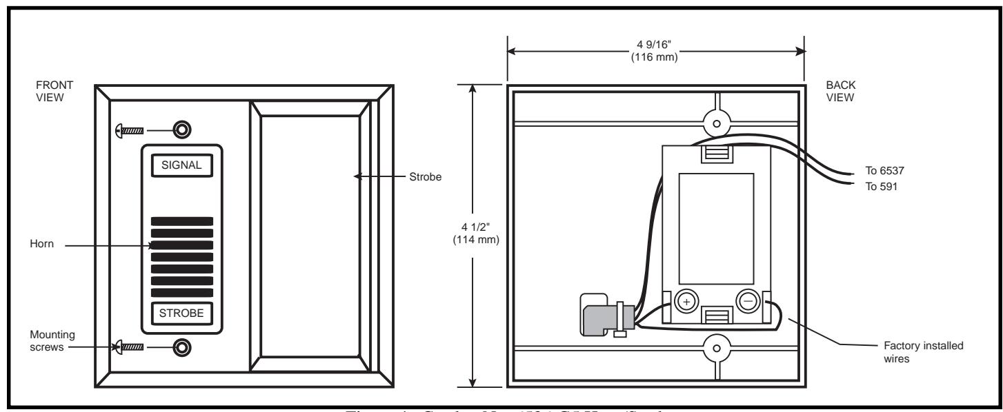
Figure 4. Catalog No. 6536-G5 Horn/Strobe