Edwards Signaling 6536-G5 Installation Instructions
Open the original PDF document
View PDF

Installation Instructions for the 6536-G5 Horn/Strobe
Description
The 6536-G5 is an audible/visual signal UL Listed for general purpose signaling applications.
Installation
A qualified electrician familiar with National Electrical Code and local code requirements must install this product. Failure to follow the safety precautions in this instruction sheet could result in product or property damage, severe personal injury or death.

WARNING
To reduce the risk of shock, do not remove lens or tamper with unit when the circuit is energized. Do not connect AC power until installation is complete.
The 6536-G5 horn/strobe (Figure 1) can be mounted on any single gang 2" x 4" (51 mm x 102 mm) electrical box, double gang 4" x 4" (102 mm x 102 mm) electrical box, or standard 4" x 4" (102 mm x 102 mm) junction box with a plaster ring.
1. Install an appropriate electrical box using suitable hardware.
2. Connect the horn/strobe wire leads and terminals (Figure 2). The horn and strobe are connected together at the factory.
NOTE: To connect the horn and strobe to different circuits, loosen the terminals, remove the two wires and cap off with wire nuts.
- 3. Mount the horn/strobe onto the electrical box. Secure it using two screws (supplied).
- 4. Perform an operational test.
Maintenance

WARNING
To reduce the risk of shock, do not remove lens or tamper with unit when the circuit is energized. Disconnect power and allow five (5) minutes for stored energy to dissipate before starting work or disassembly. High energy could be stored in the strobe circuit once it is energized.
Perform regularly scheduled testing at least twice a year or more often as dictated by local authorities having jurisdiction.
Table 1. Specifications
| Operating Voltage | 24V 50/60 Hz | 24V DC |
|---|---|---|
| Alarm Current | 175 mA | 125 mA |
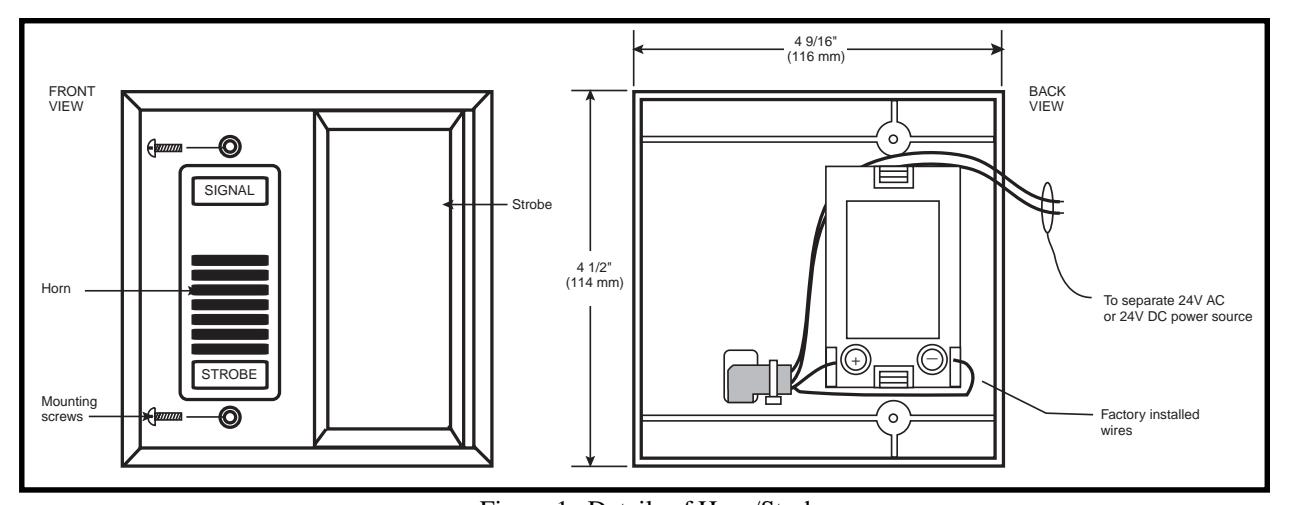
Figure 1. Details of Horn/Strobe
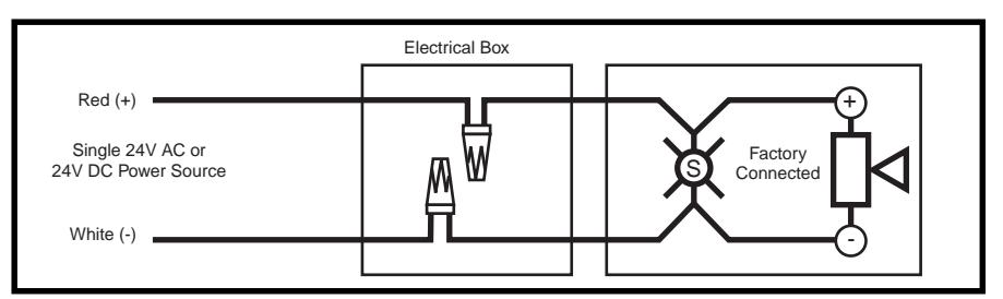
Figure 2. Connecting the Horn and Strobe