Edwards Signaling 5535 Installation Instructions
Open the original PDF document
View PDFInstallation Instructions for Remote Amplifiers Catalog Series 5535

Description and Operation
Edwards remote amplifiers are designed to accept tones, voice, or music inputs from 5541 System control units or tones from 5540 Series Tone Generators. The amplifiers convert the input signals to 70V line output (up to 15 watts) to sound on speakers in remote locations. The remote amplifiers are UL listed and CSA certified as audible signal appliances for general signaling (non-fire alarm) use.
Mechanical Specifications
Weight ............................................................. 7 Pounds (3.2 kg) Variable Ambient Temp. ............ -31F to +151F (-35C to +66C)
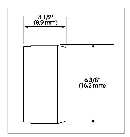
Figure 1. Dimensions
Electrical Specifications
| INPUT POWER | |||
|---|---|---|---|
| Typical Current | |||
| Catalog | Standby | Tone On | |
| Number | Voltage | Current (A) | Current (A) |
| 5535-N5 | 120V 60 Hz | .11 | .31 |
| 120V 50 Hz | .30 | .40 | |
| 24V DC | .02 | .60 | |
| 5535-R5 | 240V 60 Hz | .053 | .20 |
| 240V 50 Hz | .064 | .25 | |
| 24V DC | .018 | .60 | |
Installation
Installation should be completed in accordance with applicable local codes and the latest edition of either NFPA 70, National Electrical Code, or CSA C22.1, Canadian Electrical Code.
Each 5535 Series Remote Amplifier may be mounted to any flat surface or may be used as a freestanding unit mounted to a rigid pipe.
NOTE: During installation, take care not to damage the components on the printed circuit board.
-
1. Mount Adaptatone (Figure 2).
- a. Remove (4) cover screws from the signal box and lift off cover.
- b. Flat Surface Mounting . Secure unit to mounting surface at the (2) mounting holes in rear of box with furnished O-rings and #10 X 1 1/2" (38 mm) screws (supplied). For mounting to dry wall or concrete surfaces, use furnished O-rings and suitable hardware (not supplied).
- c. Rigid Pipe Mounting . Seal the (2) mounting holes in rear of box with (2) furnished O-rings and #12 X 3/8" (9.5 mm) long screws.
Remove the center knockout in lower wall of box and mount box to a 1/2" (12.7 mm) conduit pipe using suitable connector (not supplied).
2. Install wires through a knockout hole in the bottom of the box when the signal is mounted to a flat surface, or through the pipe when the signal is freestanding. In areas of high electrical noise, use shielded audio cable.
-
3. Wire Adaptatone as follows:
- a. Connecting 5535 Amplifier(s) to 5541 System Control Units (Figure 3).
Connect the wires from the 5541 System Control unit TB2-Audio Out, L and H terminals to the 5535 Remote Amplifier TB2-L and H terminals. Observe polarity. For other system connections, see instructions P-047550- 0858 shipped with the 5541 System Control Units.
b. Connecting 5535 Amplifier(s) to 5541B System Control Units (Figure 3).
Connect the wires from the 5541B System Control unit TB2 Area 1 Audio Out terminals to the 5535 Remote Amplifier TB2-L and H terminals. Observe polarity. For other system connections, see instructions P-047550- 1558 shipped with the 5541B System Control Units.
c. Connecting 5535 Remote Amplifier(s) to a Series 5540 or 5540A Central Tone Generator (Figure 4).
Connect the wires from the Central Tone Generator TB2- HI and LO terminals to the 5535 Remote Amplifier TB2- H and L terminals. Observe polarity. For other system connections, see instructions P-047550-0179 shipped with 5540 Series Central Tone Generators or P-047550- 0228 shipped with 5540A Series Central Tone Generators.
d. Connecting 5535 Remote Amplifier(s) to a Series 5540B Central Tone Generator (Figure 4).
Connect the wires from the Central Tone Generator TS1- 9 and 10 Tone Out terminals to the 5535 Remote Amplifier TB2-H and L terminals. Observe polarity. For other system connections, see instructions P-047550- 1550 shipped with 5540B Series Central Tone Generators.
e. Speaker Connections (Figure 3 or 4). The Remote Amplifier provides up to 15 watts audio power to 70V line speakers. For best service use the Edwards 5547 and/or 5551B Series Speakers.
Connect the speakers to the two yellow wires coming from the transformer that is mounted on the Remote Amplifier's printed circuit board.
f. Power Supply Connections (Figure 3 or 4).

WARNING
To prevent electrical shock, do not apply power until all system wiring is completed and all covers are secured.
Connect the AC power source wires to the two black pigtailed wires coming from the transformer on the inside cover of the remote amplifier.
g. Standby Power (Optional) (Figure 3).
A 2.5 to 3 ampere hour 24V DC battery is recommended for standby power. This type of battery provides 24 hours of standby service.
Connect standby power to 5535 TB1-B(+) and TB1-B(-) terminals. Observe polarity.
- 4. Adjust volume level, if desired, by turning potentiometer (Figure 3 or 4).
- 5. Replace the signal box cover.
-
6. Verify operability as follows.
- a. Initiate a signal and verify that is sounds on all the speakers connected to the Remote Amplifier. Reset initiating device.
- b. If standby power is used, verify that it will function properly. Remove the 120V AC or 240V AC power, initiate a signal and verify that is sounds on all speakers that are connected to a Remote Amplifier. Reset the initiating device and restore 120V AC or 240V AC power.
Maintenance and Test

WARNING
To prevent electrical shock, ensure that power is disconnected before cleaning inside of unit.
Examine the unit semi-annually for accumulation of dirt. Clean if necessary.
The Remote Amplifier should be tested annually or as required by the authority having jurisdiction to ensure continuous service.
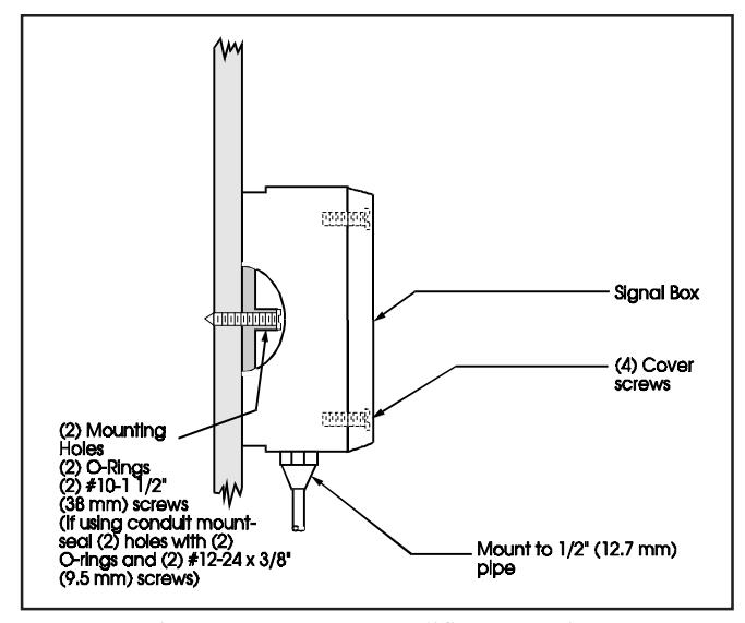
Figure 2. Remote Amplifier Mounting.
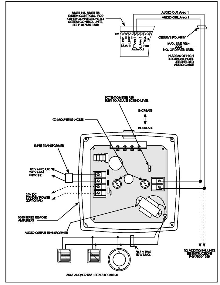
Figure 3. Remote Amplifier Wiring to System Control Unit (5541B Series Shown)
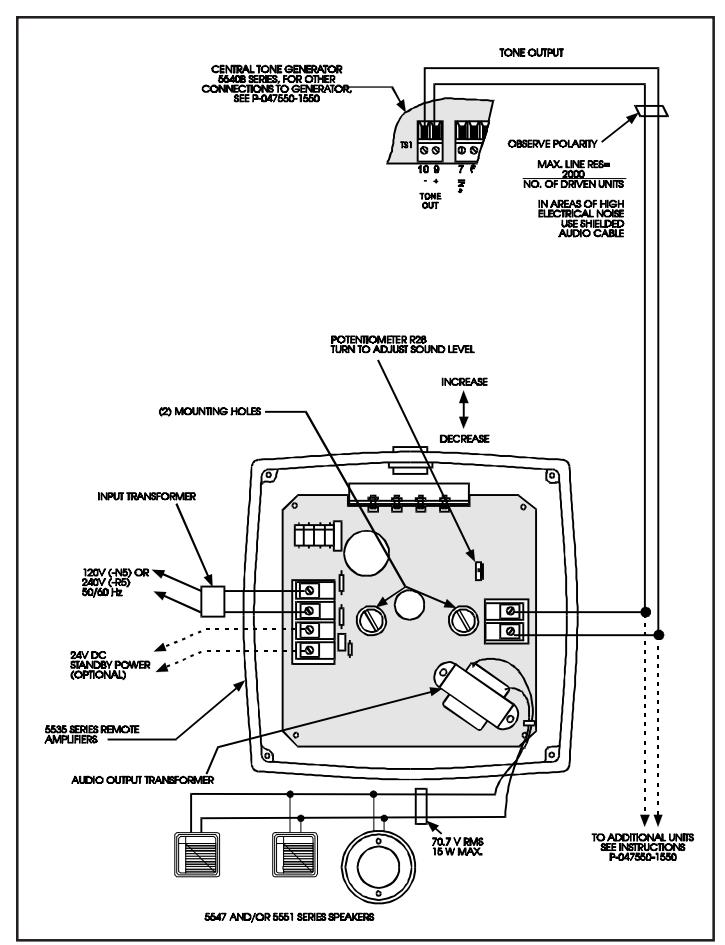
Figure 4. Remote Amplifier Wiring to Central Tone Generator (5540B Series Shown)