Edwards Signaling 5510M Installation Instructions
Open the original PDF document
View PDF

Description and Operation
Edwards Remote Audio Signal Converter is intended for industrial applications where high audible output and microcomputer reliability are required.
Catalog Series 5510M are UL and cUL Listed as Audible Signal Appliances for use in the following hazardous locations.
|
Catalog
Number |
Hazardous
Locations |
Temp.
Code |
|---|---|---|
| 5510M-25Y6 | Class I, Div. 2, Groups A, B, C, D | T4 (135C) |
| 5510M-70Y6 |
Class II, Div. 2, Groups F, G
Class III, Div. 1 and 2 |
T5 (100C) |
The Audio Signal Converter operates from local power. The 5510M-25Y6 converts 25V RMS audio signal to 10V RMS for use with the 5532M Adaptatone Speaker/Amplifiers. The 5510M-70Y6 converts a 70V RMS audio signal to 10V RMS for use with the Edwards 5532M Adaptatone Speaker/Amplifiers or other 10V RMS applications.
Specifications
| Weight | 6 Pounds (2.7 kg) |
|---|---|
|
Hazardous Locations, UL Stant
Ambient Temp + |
|
| Non-Hazardous Locations Variable Ambient Temp4 | 40F to +151F (-40C to +66C) |
Electrical Specifications
| Current (A) | ||||
|---|---|---|---|---|
| Voltage | Standby | Tone On | ||
| Remote Audio Signal Converter | ||||
| 125V DC* | 0.10 | 0.21 | ||
| 250V DC* | 0.02 | 0.10 | ||
| 120V AC 50/60 Hz | 0.10 | 0.32 | ||
| 240V AC 50/60 Hz | 0.10 | 0.20 | ||
Installation
The Adaptatone may be mounted to any flat surface or may be used as a freestanding unit mounted to a rigid pipe. The Adaptatone must be installed in accordance with the latest edition of the National Electrical Code or other regulations applicable to the country and locality of installation and by a trained and qualified electrician.
NOTE: The increased resistance due to long wire runs needs to be accounted for in sizing wire. Consult Applications Engineering for details.
-
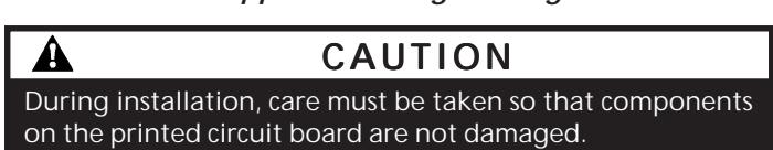
1. Mount Adaptatone as shown in Figure 1.
- a. Flat Surface Mounting . Secure unit to mounting surface using the (4) mounting holes in the mounting plate on the rear of the box. Use the #10 x 3" (76 mm) wood screws (furnished loose) or other hardware (not supplied) suitable for the mounting surface.
- b. Rigid Pipe Mounting . Loosen the (4) cover screws from the signal box and lift off signal box cover.
NOTE: Cover screws are captive. Do not remove from cover.
Remove the center knockout in lower wall of box and mount box to a 1/2" (12.7 mm) conduit pipe using suitable connector.
2. Install wires through a knockout hole in the bottom of the box from a raceway that is, with its connections to the 1/2" (12.7 mm) conduit knockout hole, approved for the same degree of protection and enclosure type needed by the application. Use the provided plastic tie-wrap, on the barrier to the electronics, to separate incoming power leads from signal and tone initiating leads, per NEC (Figures 4, 5 and 6).
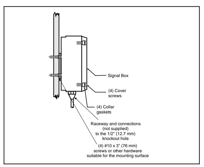
Figure 1. Adaptatone Mounting
A
WARNING
To prevent fire and shock, wire the Adaptatone only as described in this installation instruction.
-
3. Wire as follows referring to Figures 2 through 5:
- a. Connect green and yellow striped earth-ground wires to earth-ground.
- b. See Figure 4. For 5510M-25Y6, connect 25V RMS audio input (+) to the AUD (+) terminal on the Audio Coupler Board. Connect 25V RMS audio input (-) to the AUD (-) terminal on the Audio Coupler Board.
See Figure 4. For 5510M-70Y6 , connect 70V RMS audio input (+) to the AUD (+) terminal on the Aduio Coupler Board. Connect 70V RMS audio input (-) to the AUD (-) terminal on the Audio Coupler Board.
- c. See Figure 4. Connect 10V RMS audio output (+) to terminal A on the Audio Coupler Board. Connect 10V RMS audio output (-) to terminal B on the Audio Coupler Board.
- d. Connect incoming power to wire leads using a butt splice or other method listed, certified, or otherwise approved by local authorities. Leads are black for line and white for neutral. See Figure 2
- e. Optional. Connect external 24V DC battery (not supplied) in series with separate diode assembly part 2600010 (supplied) to TB1 terminals 3 and 4 on the main board as shown in Figure 7 and marked on the diode assembly.
NOTE: Terminal Block TB1 can be unplugged from the main board to complete wiring as shown in Figure 2.
A
WARNING
To ensure integrity of the enclosure: Ensure the cover gasket, part number P-007549-0069, is adhered into groove at cover perimeter before replacing the signal box cover.
Ensure that the (4) collar gaskets, part number P-041930-0362, are in place on each cover screw before securing the signal box cover.
When securing cover, start screws by hand, making sure they are threaded into tapped holes in housing bosses before securing with a screwdriver. Torque signal box cover screws to a minimum of 20 in-lbs. This ensures the required tight fit.
- 4. Tightly secure the signal box cover using (4) retained cover screws.
- 5. Torque signal box cover screws to a minimum of 20 in-lbs.
- Verify operability.
Maintenance and Test

WARNING
Ensure that power is disconnected before cleaning inside of unit.
Examine the unit semi-annually for accumulation of dirt. Clean if necessary.
The Adaptatone should be tested annually or as required by the authority having jurisdiction to ensure continuous service.
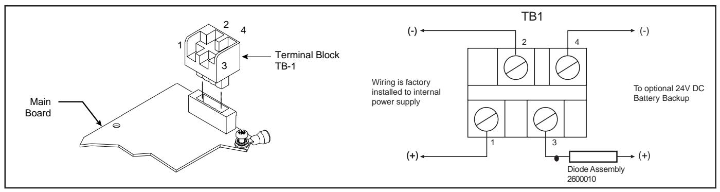
Figure 2. Wiring to Terminal Block TB-1
P/N 3100359 ISSUE 2 PAGE 2
Figure 3. Wiring the 5510M Series Remote Signal Converter
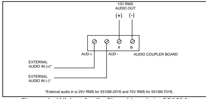
Figure 4. Wiring Audio Signal Leads to 5510M
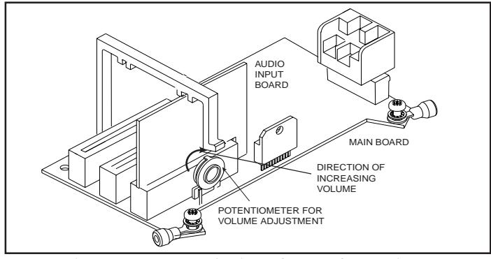
Figure 5. 5510M Series PC Board Locations
PAGE 3 P/N 3100359 ISSUE 2