Edwards Signaling 53D-GW Installation Instructions
Open the original PDF document
View PDF

Cheshire, CT 06410 203-699-3300 (Ph) 203-699-3365 (Cust. Serv. Fax) 203-699-3078 (Tech. Serv. Fax)
Installation and Maintenance Instructions for the Catalog 53D-GW AdaptaBeacon® Signal
Description
The catalog number 53D-GW AdaptaBeacon signal is an in-rush current limited, DC-operated, rotating light. The signal may be either conduit mounted or direct surface mounted and is suitable for indoor installation. A hardware kit is included with the signal for direct mounting applications.
Specifications
|
Catalog
Number |
Voltage | Current |
Dome
Replacement |
Lamp
Replacement |
|---|---|---|---|---|
| 53DA-GW | 24 - 28V DC | 1.0A | 52-LA | Cat. No. 1638 |
| 53DB-GW | 24 - 28V DC | 1.0A | 52-LB | Cat. No. 1638 |
| 53DC-GW | 24 - 28V DC | 1.0A | 52-LC | Cat. No. 1638 |
| 53DG-GW | 24 - 28V DC | 1.0A | 52-LG | Cat. No. 1638 |
| 53DM-GW | 24 - 28V DC | 1.0A | 52-LM | Cat. No. 1638 |
| 53DR-GW | 24 - 28V DC | 1.0A | 52-LR | Cat. No. 1638 |
Installation

CAUTION
Ensure that power is disconnected before installing the signal.
- 1. Remove the screw in the clamp ring, remove the ring and lift off the dome (Figure 1).
- 2. Install the base using one of the following applicable procedures.
Conduit Mounting
- a. Route the wiring from the required power source for the signal (refer to the signal's label for voltage rating) through a 1/2" NPT conduit (not supplied) and through the conduit entrance hole in the base.
- b. Install the base on the conduit.
Direct Surface Mounting
- a. Remove the two knockouts for the mounting screws from the bottom of the base. See Figure 1 for the location of the knockouts.
- b. Place the gasket provided in the hardware kit on the mounting surface and mark the center of the three holes in the gasket on the surface. Remove the gasket and drill a 3/8" hole at each of the marked positions.
- c. Install the two rubber expansion plugs provided in the hardware kit into the two outer holes in the mounting surface as indicated in Figure 2.
- d. Route the wiring from the required power source for the signal (refer to the signal's label for the voltage rating) through the center holes in the mounting surface, gasket and base.
- e. Align the holes in the gasket with the holes in the base. Insert the two screws with lockwashers provided in the hardware kit through the mounting holes inside the base and align the screws with the rubber expansion plugs as shown in Figure 2. Press the base firmly against the mounting surface and tighten the screws.
- 3. Using wire nuts (not supplied), connect one of the signal's red wire leads to the incoming positive (+) power source lead and the other to the outgoing positive (+) power source for the next unit or an endof-line resistor. Connect one of the signals' white wire leads to the incoming negative (-) power source lead and the other to the outgoing negative (-) power source for the next unit or an end-of-line resistor.
NOTE: Wire run must be broken at each unit for electrical supervision.
Maintenance

CAUTION
Always disconnect power before disassembling the signal.
Lamp Replacement
-
1. Replace the lamp as follows (Refer to Specifications for the required lamp.):
- a. Disconnect power.
- b. Remove the screw in the clamp ring and remove the ring.
- c. Lift the dome off the signal.
- d. Replace the lamp.

CAUTION
Do NOT use abrasive materials or cleaners to clean the dome.
Cleaning
The dome should be periodically cleaned to maintain light visibility. The dome may be cleaned with a soft cloth or sponge using a mild detergent. Dry the dome thoroughly before replacing.
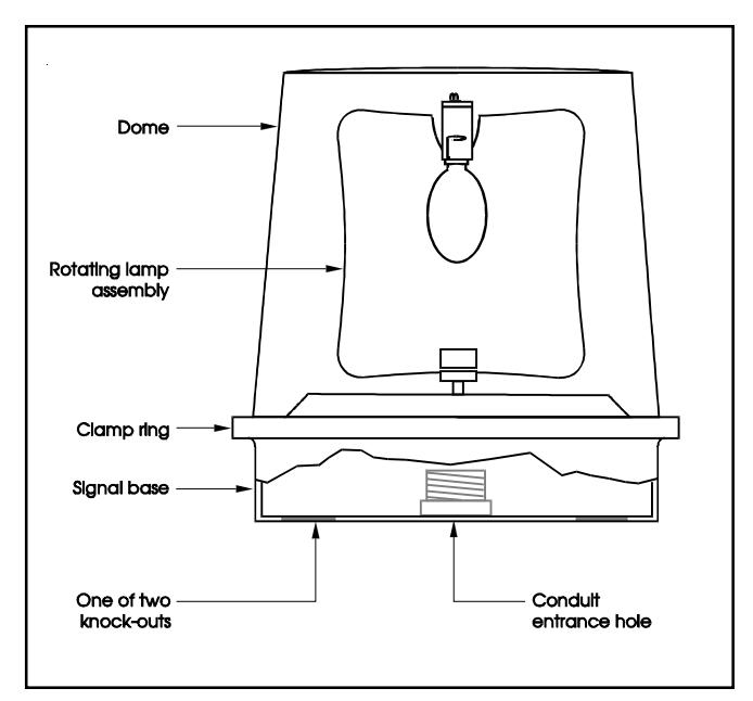
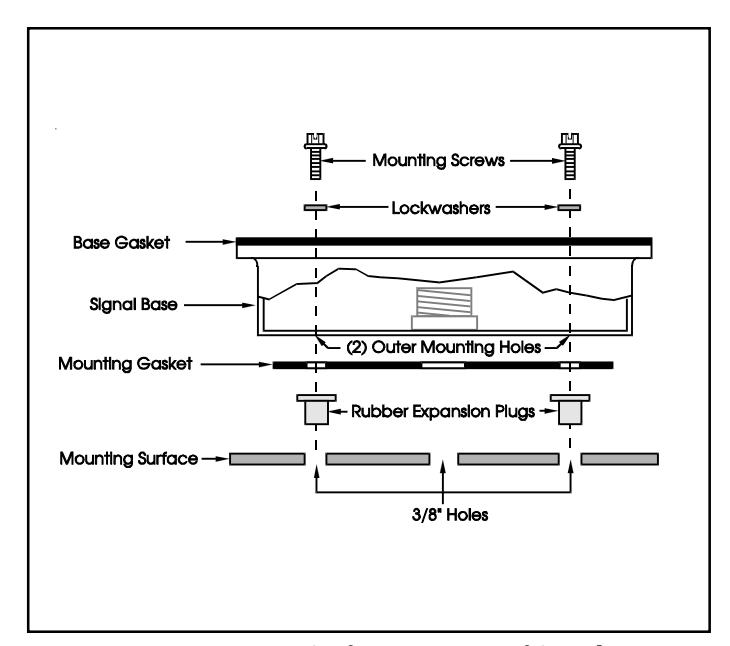
Figure 1. Catalog 53D-GW Rotating Light Figure 2. Direct Surface Mounting of Signal