Edwards Signaling 53 Series Installation Instructions
Open the original PDF document
View PDF

Installation and Maintenance Instructions for Catalog Series 53 AdaptaBeacon® Signals
Description
The catalog series 53 Adaptabeacon signals are dc operated rotating lights. The signals may either be conduit mounted or direct surface mounted and are suitable for indoor or outdoor (weatherproof) installation. A hardware kit is included with the signals for direct mounting applications.
Specifications
|
Catalog
Number |
Rated
Voltage |
Current |
|---|---|---|
| 53(*)-E1 | 12V DC | 1.8A |
| 53(*)-G1 | 24V DC | 1.0A |
| 53(*)-FY | 36V DC | 1.0A |
| 53(*)-K1 | 48V DC | 0.7A |
* The letter in this position of the catalog number signifies the color of the supplied dome. A - amber, B - blue, C - clear, G - green, M - magenta, or R - red
Installation
CAUTION
Ensure that power is disconnected before installing the signal.
- 1. See Figure 1. Remove the screw in the clamp ring, remove the ring and lift off the dome.
- 2. Install the base using one of the following applicable procedures.
CAUTION
When installing indoors, the signal may be mounted with the dome facing either directly up or down. For outdoor installation, the signal must be installed with the dome facing directly up.
Conduit Mounting
- a. Route the wiring from the required power source for the signal (refer to the signal's label for voltage rating) through a 1/2" (13 mm) NPT conduit (not supplied) and through the conduit entrance hole in the base.
- b. Install the base on the conduit.
Direct Surface Mounting
- a. Remove the two knock-outs for the mounting screws from the bottom of the base. See Figure 1 for the location of knock-outs.
- b. Place the gasket provided in the hardware kit on the mounting surface and mark the center of the three holes in the gasket on the surface. Remove the gasket and drill a 3/8" (9.5 mm) hole at each of the marked positions.
- c. Install the two rubber expansion plugs provided in the hardware kit into the two outer holes in the mounting surface as indicated in Figure 2.
- d. Route the wiring from the required power source for the signal (refer to the signal's label for the voltage rating) through the center holes in the mounting surface, gasket and base.
- e. Align the holes in the gasket with the holes in the base. Insert the two screws with lockwashers provided in the hardware kit through the mounting holes inside the base and align the screws with the rubber expansion plugs as shown in Figure 2. Press the base firmly against the mounting surface.
- 3. Using wire nuts (not supplied), connect the signal's red wire lead to the positive (+) power source lead and connect the white wire lead to the negative (-) power source wire. Place the connected wires inside of the base and reassemble the signal on the base.
Maintenance
CAUTION
Always disconnect power before disassembling the signal.
Lamp Replacement
Refer to the "Replacement Parts" for the required lamp. Disconnect the power, remove the screw in the clamp ring, remove the ring and lift the dome off the signal. Replace the lamp.
Cleaning
CAUTION
Abrasive materials or cleaners must not be used to clean the dome.
The signal's dome should be periodically cleaned to maintain optimum light visibility. The dome may be cleaned with a soft cloth or sponge using a mild detergent. Dry the dome thoroughly before replacing.
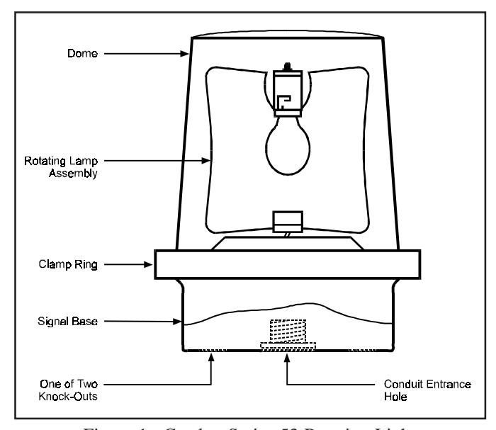
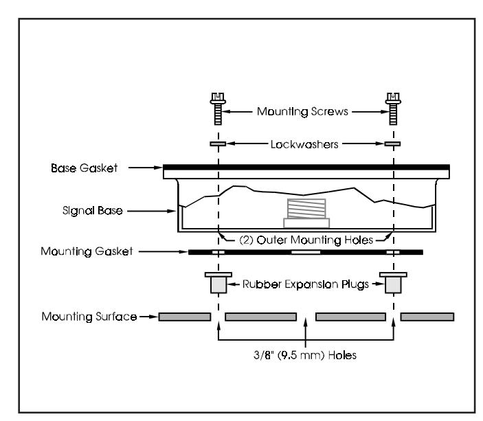
Figure 1. Catalog Series 53 Rotating Light Figure 2. Direct Surface Mounting of Signal
Replacement Parts
The replacement parts listed below for the 53 series signals are available from your local Edwards distributor.
| Catalog Number | Replacement Lamp | Replacement Dome |
|---|---|---|
| 53(*)-E1 | 1076 | 52-L(*) |
| 53(*)-G1 | 1638 | |
| 53(*)-FY | 1062 | |
| 53(*)-K1 | P-041695-0086 |
* Specify color of the replacement dome by adding the letter A, B, C, G, M or R to the catalog number; for example, a red dome for the 53(*)-E1 series signal is 52-LR.