Edwards Signaling 51XBRF Series Flashing LED Signal Installation Sheet
Open the original PDF document
View PDF

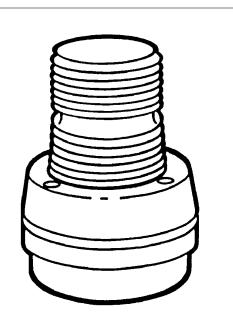
51XBRF Series Flashing LED Signal Installation Sheet
Description
The 51XBRF Series Flashing LED Signals are AC and DC operated combination flashing LEDs with horns. They feature optically designed polycarbonate lenses. These signals are suitable for installation in a permanent outdoor or indoor application. Their base allows direct surface mounting, mounting on 1/2 in. NPT conduit, or mounting on a 4 in. (102 mm) octagon box. A hardware kit is included with the signals for direct surface mounting applications.
Replacement horns, flasher modules, and lenses are available for the signals. Refer to the table at the end of these instructions for details.
PLC compatibility
The electrical input load requirements for PLC compatible signaling devices are listed in Table 1. Signaling devices may be directly connected to output cards that meet the input load requirements.
Table 1: PLC compatibility
| Catalog number | 51XBRF*120A 51XBRF*24D | |
| Operating voltage | 120 VAC | 24 VDC |
| Off state leakage current | 10 mA max. | 10 mA max. |
| Continuous on current | 175 mA | 275 mA |
| Surge (inrush/duration) | 50 A / 260 µs | 10 A / 120 µs |
The letter in this position signifies lens and LED color: A = amber, B = blue, W = white, G = green or R = red
Installation
Install this unit in accordance with the latest edition of the NFPA 70 National Electrical Code and local codes. Prior to mounting the signal base, the signal must be removed from the base. The base can be mounted using one of the following methods:
- Direct surface mount
- Mounted on 1/2 in. NPT conduit
- Mounted on a 4 in. octagon box
WARNINGS
- To prevent electrical shock, ensure that power is disconnected before installing the signals.
- To prevent leakage and potential electrical shock, use care when disassembling the signal to prevent tearing of the permanently affixed gaskets provided for weatherproofing.
To remove the signal from the base:
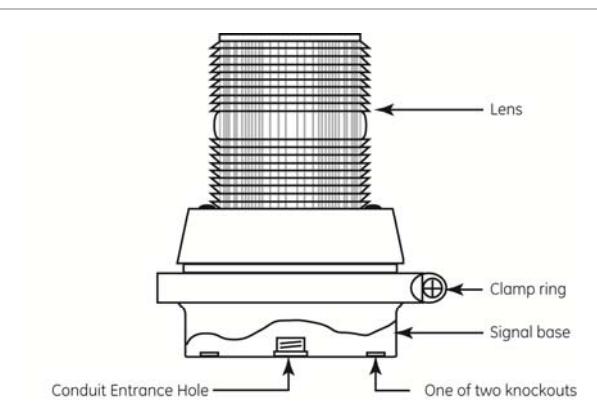
- 1. Remove the screw in the clamp ring, and then remove the ring. See Figure 1.
- 2. Carefully lift the lens/lamp assembly off the base.
- 3. Install the signal base using one of the following mounting procedures.
Figure 1: 51XBRF series flashing light with horn
To direct surface mount the base:
- 1. Remove the two knockouts for mounting screws from the signal base bottom. See Figure 1 for the location of the knockouts.
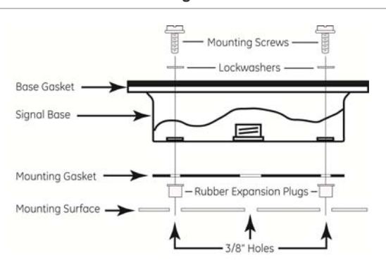
- 2. Place the mounting gasket provided in the hardware kit on the mounting surface, and mark the center of the three holes in the gasket onto the mounting surface. Remove the gasket, and then drill a 3/8 in. (9.5 mm) hole at each of the marked positions. See Figure 2.
- 3. Install the two rubber expansion plugs provided in the hardware kit into the two outer holes in the mounting surface as shown in Figure 2.
- 4. Route the field wiring from the required power source for the signal (refer to its label for the voltage rating) through the center holes in the mounting surface, mounting gasket, and signal base.
- 5. Align the holes in the mounting gasket with the holes in the signal base. Insert the two screws with lock washers provided in the hardware kit through the mounting holes inside the base and align the screws with the rubber expansion plugs as shown in Figure 2.
- 6. Press the base firmly against the mounting surface and tighten the screws.
- 7. Proceed to "Wiring" below for wiring connections.
Figure 2: Direct surface mounting
Note: For direct surface mounting, the 51XBRF series signals may be installed in any position.
WARNING: To prevent leakage and a potential shock hazard, when mounting outdoors the signal must be installed with the lens or dome facing directly up.
To mount on ½ in. NPT conduit:
- 1. Route the field wiring from the required power source for the signal (refer to its label for the voltage rating) through a ½ in. NPT conduit (not supplied) and through the center hole in the signal base.
- 2. Install the base on the conduit.
- 3. Proceed to "Wiring" below for wiring connections.
To mount on a 4 in. (102 mm) octagon box (indoor installation only):
- 1. Remove the two knockouts for mounting screws from the signal base bottom. See Figure 1 for the location of the knockouts.
- 2. Route the field wiring from the required power source for the signal (refer to its label for the voltage rating) through the center hole in the base.
- 3. Fasten the base to the octagon box (not supplied) by installing the screws supplied with the box through the holes in the base.
- 4. Proceed to "Wiring" below for wiring connections.
Wiring
To wire 24 VDC models:
- 1. Using wire nuts (not supplied), connect the signal's red wire to the positive (+) power source lead and connect the black wire lead to the negative (−) power source wire.
- 2. Neatly place the connected wires inside the base, and then carefully position the lens/lamp assembly onto the base.
- 3. Turn on the power, and then verify that the signal operates properly.
To wire 120 VAC models:
- 1. Using wire nuts (not supplied), connect the signal's black wire to hot power source lead and connect the white wire lead to the neutral power source wire.
- 2. Connect the green wire to the earth ground connection.
- 3. Neatly place the connected wires inside the base, and then carefully position the lens/lamp assembly onto the base.
- 4. Turn on the power, and then verify that the signal operates properly.
Maintenance
WARNINGS
- To prevent electrical shock, ensure that power is disconnected before installing the signal.
- To prevent leakage and potential electrical shock, use care when disassembling the signal to prevent tearing of the permanently affixed gaskets provided for weatherproofing.
Horn replacement
Refer to Table 2 for the required horn. After disconnecting power, remove the old horn and attach the new one. Reattach the horn module wiring to the flasher module wiring.
Cleaning
Caution: To prevent damage to the lens, do not use abrasive materials or cleaners.
The signal lens should be cleaned periodically to maintain optimum light visibility. It can be cleaned with a soft cloth or sponge using mild detergent. Dry the lens completely before replacing it.
Table 2: Replacement parts
| Catalog Number | 51XBRF*120A | 51XBRF*24D |
|---|---|---|
| Replacement horn | 123A-N5 | 118-G1 |
| Replacement lens | 92-L* | 92-L* |
| Solid state flasher module | P-041917-0026 | P-041917-0028 |
* Letter in this position designates lens and LED color = A = amber, B = blue, W = white, G = green, R = red
Troubleshooting
If the LED is flashing and the horn is not buzzing then the solid state flasher needs to be replaced. If after the replacement of solid state flasher the horn is still not buzzing, then the horn needs to be replaced. If the LED is not flashing and the horn is buzzing, then the LED circuit is damaged (the LED circuit is not offered as replacement part).
Specifications
| Catalog number | Electrical specs | Color |
|---|---|---|
| 51XBRFA120A | 120 VAC, 0.175 A | Amber |
| 51XBRFB120A | 120 VAC, 0.175 A | Blue |
| 51XBRFG120A | 120 VAC, 0.175 A | Green |
| 51XBRFR120A | 120 VAC, 0.175 A | Red |
| 51XBRFW120A | 120 VAC, 0.175 A | White |
| 51XBRFA24D | 24 VDC, 0.275 A | Amber |
| 51XBRFB24D | 24 VDC, 0.275 A | Blue |
| 51XBRFG24D | 24 VDC, 0.275 A | Green |
| 51XBRFR24D | 24 VDC, 0.275 A | Red |
| 51XBRFW24D | 24 VDC, 0.275 A | White |
Regulatory information
| Manufacturer |
Edwards, A Division of UTC Fire & Security
Americas Corporation, Inc. 8985 Town Center Parkway, Bradenton, FL 34202, USA |
|---|---|
|
North American
standards |
UL 1638 |
Contact information
For contact information see our Web site: www.edwardssignaling.com