Edwards Signaling 51SIN Series Installation Instructions
Open the original PDF document
View PDF

Cheshire, CT 06410 203-699-3300 (Ph) 203-699-3365 (Cust. Serv. Fax) 203-699-3078 (Tech. Serv. Fax)
Installation Instructions for Catalog Series 51SIN Adaptabeacon<sup>®</sup> Signals
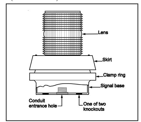
Figure 1. Catalog Series 51SIN
Specifications
|
Catalog
Number |
Ratings |
Lamp
Life**** |
|---|---|---|
| 51SIN(*)-G1 |
24V DC
0.80A .402 Lumens*** |
3,180 Hours |
| 51SIN(*)-N5-40W** |
120V 50/60 Hz
0.29A 265 Lumens*** |
25,000 Hours |
* Letter in this position signifies the color of the lens -- R - red, A
- amber, B blue, C clear, G green, or M magenta.
- **UL and cUL listed
- ***Bulb manufacturer's lumen rating
- ****Projected lamp life based on manufacturer's calculated lamp life at 65 FPM and 50% duty cycle.
Description
Catalog Series 51SIN Adaptabeacon signals are general purpose visual/audible signaling appliances. The 51SIN series are combination steady-on lights with horn. The signals are PLC compatible and can be flashed either from a PLC or an external relay.
The 51SIN series signals are suitable for indoor or outdoor (weatherproof) installation and utilize a standard base that allows direct surface mounting, mounting on a 4" (102 mm) octagon box, or mounting on 1/2" (13 mm) NPT conduit. For outdoor installation, the signals must be mounted on conduit.

WARNING
To prevent electrical shock, ensure that power is disconnected before installing the signal.

WARNING
To prevent leakage and a potential shock hazard, use care when disassembling the signal to prevent tearing of the permanently affixed weatherproof gaskets.
Installation
Install in accordance with the latest edition of the National Electrical Code and local regulations.
- See Figure 1. Remove the screw in the clamp ring, remove the ring, and lift the lens/lamp assembly off of the base.
- 2. For indoor installation, the signal may be direct surface mounted, mounted on a 4" (102 mm) octagon box, or mounted on 1/2" (13 mm) NPT conduit. For outdoor (weatherproof) installation, the signal must be conduit mounted. Install the signal base using one of the following applicable mounting procedures.
a. Direct Surface Mounting (indoor installation only)
Remove the two knockouts for mounting screws from the bottom of the signal base.
Route the field wiring from the required power source through the conduit entrance hole in the base.
Fasten the base to the surface by installing two #10 wood screws (not supplied) or other suitable hardware through the knockout holes in the base. Proceed to step 3 for wiring connections.
b. Mounting on a 4" (102 mm) Octagon Box (indoor installation only)
Remove the two knockouts for mounting screws from the bottom of the signal base.
Route the field wiring from the required power source through the conduit entrance hole in the base.
Fasten the base to the octagon box (not supplied) by installing the screws supplied with the box through the knockout holes in the base. Proceed to step 3 for wiring connections.
Mounting on 1/2" (13 mm) NPT Conduit (indoor or outdoor installation)

WARNING
To prevent leakage and a potential shock hazard when mounting outdoors, install the signal with the dome facing directly up.
Route the field wiring from the required power source through the conduit entrance hole in the
base. Install the base on the conduit (not supplied).
- Connect the field wiring to the terminal block in the base of the unit. Polarity must be observed on DC units. Connect the green ground wire lead in accordance with local codes. Place the connected wires inside the base and reassemble the signal on the base.
- 4. Turn on power and verify that the signal operates properly.
Troubleshooting
Should the lamp fail to operate, check that power is on. If power is on, the lamp requires replacement.
Maintenance
Lamp Replacement

WARNING
To prevent electrical shock, do not remove or insert lamp when unit is energized.
Refer to the Replacement Parts section below for the required type of lamp.
- 1. Disconnect power to the signal.
- 2. Remove the three screws from the top of the skirt and lift off the lens and skirt.
3. Turn the bulb counterclockwise and pull straight up to remove.

CAUTION
To prevent property damage and injury. do not touch glass with bare fingers; grasp glass with a soft, clean cloth or with packaging supplied with the replacement lamp.
- 4. Grasping bulb with a soft, clean cloth, press into socket and turn clockwise.
- 5. Reassemble the signal.
- 6. Turn on power and verify that the signal operates properly.
Cleaning

CAUTION
To prevent damage to the lens and dome, do not use abrasive materials or cleaners.
The signal's lens and/or dome should be peridodically cleaned to maintain optimum light visibility. These items may be cleaned with a soft cloth or sponge using mild detergent. Ensure that the lens or dome is completely dry before replacing.
| Catalog Number | Replacement Part | |
|---|---|---|
| 51SIN(*)-G1 | Lamp (32W, double contact, bayonet base) P/N P-041695-0099 or Industry Trade No. 1638 | |
|
Horn
P/N P-047570-0743 |
||
| 51SIN(*)-N5-40W |
Lamp
Cat. No. 50LMP-40W or 25T8DC |
|
|
Horn
Cat. No. 123A-N5 |
||
|
51SIN(*)-G1
51SIN(*)-N5-40W |
Lens Cat. No. 92-L(*) | |
* Specify color of lens by adding one of the following letters to the catalog number: A - amber, B - blue, C - clear, G - green, M - magenta, or R - Red.