Edwards Signaling 3000SD-EK Installation Instructions
Open the original PDF document
View PDF

Installation Instructions for Cat. 3000SD Series AdaptaBeacon® Industrial Truck Light
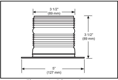
Figure 1. Dimensions
Description
The 3000SD Series visual signals are flange mount strobes designed for industrial applications and for applications where warning on a moving vehicle is necessary. The light has 80 nominal single flashes per minute at 1.5 Joules. It is a low current, 12-48V DC unit. The twist on-off lens makes for easy strobe tube and/or lens replacement.
Installation

WARNING
To prevent electrical shock, do not connect power until instructed to do so.
Installation must be in accordance with local codes. The lens should be positioned up for outdoor applications.
- 1. For side exit wiring, remove the knockout from the bottom of the flange as shown in Figure 2.
- 2. Using the template provided (Figure 3), drill 3 mounting holes and a hole for concealed wiring, if desired.
- 3. Connect the red positive (+) lead to the positive power source wire and the black negative (-) lead to the negative power source wire using the butt splices (supplied).
- 4. Align the provided gasket and the flange on the mounting holes and secure using (3) screws, lockwashers and nuts (supplied).
- 5. Apply power and verify operability.
Maintenance
The lens should be periodically cleaned using a mild detergent and water on a soft, clean, lint-free cloth.
Light Source Replacement

WARNING
To prevent electrical shock, disconnect power and wait 5 minutes for the strobe tube energy to dissipate before opening the unit.
- 1. Unscrew the lens from the base.
-
Replace the strobe tube as follows:
- a. Grasp the strobe tube by its base and pull straight up out of the strobe tube socket.
- b. Grasp the new strobe tube by the strobe tube base and press into the strobe tube socket.
- 3. Confirm O-ring gasket is seated and aligned properly on the inside of the lens.
- 4. Screw the lens onto the base.
Table 1. Electrical Specifications
| Operating Current* | Inrush Current | Repetitive Surge Current | ||||
|---|---|---|---|---|---|---|
| Voltage | RMS Current (A) | Mean Current (A) | Current (A) | Time (mS) | Current (A) | Time (mS) |
| 12V DC | 0.275 | 0.250 | 14.00 | <0.50 | 0.40 | <650 |
| 24V DC | 0.130 | 0.125 | 30.00 | <0.30 | 0.63 | <650 |
| 48V DC | 0.130 | 0.070 | 50.5 | <0.25 | 0.40 | <150 |
*Use the operating current to establish the wire gauge and standby power requirements. Consult the control unit manufacturer to determine surge and peak current effects and maximum number of strobes on the system.
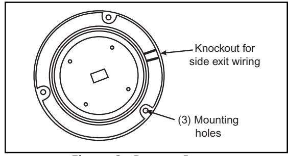
Figure 2. Beacon Base
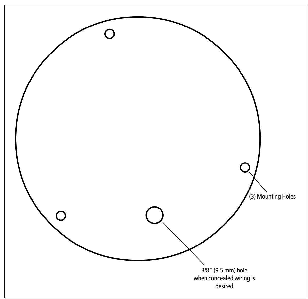
Figure 3. Mounting Template
Table 2. Replacement Parts
| Part |
Catalog
Number |
||
|---|---|---|---|
| Strobe Tube | 91B-ST | ||
| Lens | |||
| Amber | 3000LM-A | ||
| Blue | 3000LM-B | ||
| Clear | 3000LM-C | ||
| Green | 3000LM-G | ||
| Red | 3000LM-R | ||