Edwards Signaling 2453BSA Installation Instructions
Open the original PDF document
View PDFInstallation Instructions for Bell/Strobe Adapter Plate
DESCRIPTION
The bell/strobe adapter plates come equipped with an electronic strobe signal and has provisions for mounting a fire alarm bell (not supplied). The units are intended for indoor use only with compatible fire protective signaling systems.
The strobes are self-synchronized to flash at 1 fps across their full operating voltage range. Studies show that people with photosensitive conditions may experience a photoconvulsive response from multiple random flashes of light. This risk is minimized with these strobes. The strobe operates on any existing 2 wire signal circuit. Separately installed "sync control modules" are not required.
The bell/strobe adapter plate is to be installed in accordance with the latest edition of NFPA 72, National Fire Alarm Code. It is recommended that these products be installed in accordance with the requirements in the latest recognized edition of national and local fire alarm and electrical codes.
Synchronization of less than 200 milliseconds will be maintained for no less than 60 hours supervision followed by 30 minutes in alarm.
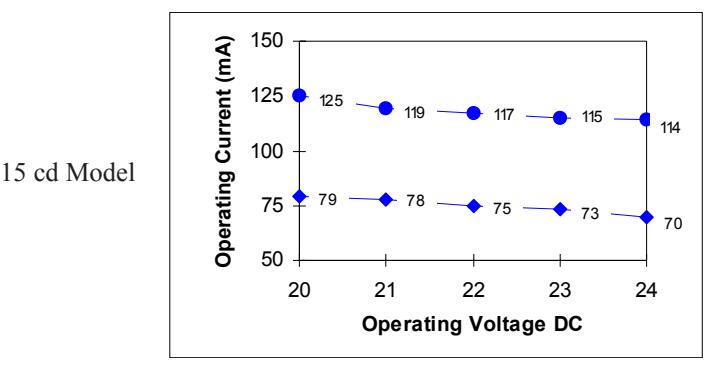
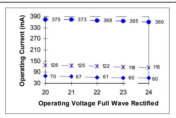
See Table 1 and Figures 1, 3 and 4 for specifications.
INSTALLATION
WARNINGS
This device will not operate without electrical power. As fires frequently cause power interruptions, discuss further safeguards with your local fire protection specialist.
To reduce the risk of shock, always disconnect all power before handling the unit.
To reduce the risk of shock, do not tamper with unit when circuit is energized. Disconnect all power and allow 5 minutes for stored energy to dissipate before handling.
- 1. Select any standard electrical box. Install the electrical box using suitable hardware.
- 2. Bring signaling circuit field wiring into the electrical box.
CAUTION
Electrical supervision requires wire run to be broken at each device. Do not loop signaling circuit field wires around bell/strobe leads.
3. See Figure 2 for wiring connections. Use wire nuts (not provided) to connect wires. The strobe must be connected to a signal circuit that outputs a constant voltage. Polarity must be observed for the unit to function properly. Figure 2 details wiring for connecting the bell and strobe to the same circuit or to separate circuits.
For additional wiring connection details, see the applicable installation instructions for the signaling modules or circuits used in the fire alarm control panel.
- 4. Mount the bell/strobe adapter plate to the electrical box using the 3/4" (19 mm) phillips head screws provided.
- 5. Mount the bell onto the adapter plate and fasten the assembly to the electrical box with the screws provided with the bell.
- 6. Replace the gong and fasten with the gong support bolt.
- 7. Apply power and activate the unit to verify that it is operating properly.
MAINTENANCE
CAUTION
Should the unit fail to operate, do not attempt repair. Contact the supplier for replacement.
Perform a visual inspection and an operational test twice a year or as directed by the local authority having jurisdiction.
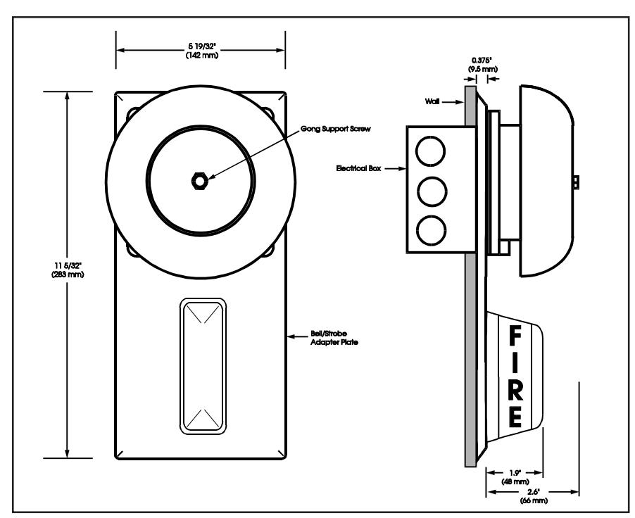
Figure 1. Detailed View

Same Signal Circuit
The bell and strobe can be connected to the same signal circuit (as shown) if the circuit is configured for continuous signal operation.
Caution: Electrical supervision requires wire run to be broken at each device. Do not loop signal circuit field wires around the Bell/Strobe unit leads.
Separate Signal Circuits
The bell and strobe can be connected to different signal circuits (as shown). The strobe is designed to be used on circuits that output a constant voltage. Do not connect the strobe to a coded or pulsating voltage. Caution: Electrical supervision requires wire run to be broken at each device. Do not loop signal circuit field wires around the Bell/Strobe unit leads.
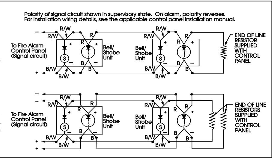
Figure 2. Connecting Strobe Unit
Table 1. Specifications
| Operating Voltage | 20-24V DC | ||||
|---|---|---|---|---|---|
| Operating Current | See Figure 3 | ||||
| Flash Rate (per second) | 1 fps (synchronized) | ||||
| 3A | 5A* | 7A | 8A | ||
| Light Output (cd) | UL 1971 | 30 cd wall | 15 cd | 15 cd wall | 110 cd wall |
| UL 1638 | 30 cd | not rated | 75 cd | 120 cd | |
| ULC S526 | 30 cd | 15 cd | 75 cd | 120 cd | |
| Operating Environment | Indoor 93% relative humidity @ 86F (30C), 32F to 120F (0C to | ||||
| 49C) variable ambient temperature | |||||
* The 5A model is for wall mount use only.
NOTE: This equipment has been tested and found to comply with the limits for a Class A digital device, pursuant to Part 15 of the FCC Rules. These limits are designed to provide reasonable protection against harmful interference when the equipment is operated in a commercial environment. This equipment generates, uses and can radiate radio frequency energy and, if not installed and used in accordance with the instruction manual, may cause harmful intereference to radio communications. Operation of this equipment in a residential area is likely to cause harmful interference in which case the user will be required to correct the interference at his own expense.
CAUTION: Changes or modifications to this equipment not expressly approved by the party responsible for compliance could void the user's authority to operate the equipment.
Table 2. Bell/Strobe Adapter Plates
| Indoor Bell/Strobe Adapter Plate, | 403-3A-R |
|---|---|
| 30 cd, Red | XLS403-3A-R |
| 2453BSA-30-R | |
| BS-3AR | |
| Indoor Bell/Strobe Adapter Plate, | 403-5A-R |
| 15 cd, Red | XLS403-5A-R |
| BS-5AR | |
| Indoor Bell/Strobe Adapter Plate, | 403-7A-R |
| 15/75 cd, Red | XLS403-7A-R |
| 2453BSA-15/75-R | |
| BS-7AR | |
| Indoor Bell/Strobe Adapter Plate, | 403-8A-R |
| 110 cd, Red | XLS403-8A-R |
| 2453BSA-110-R | |
| BS-8AR |
Peak Inrush Current @ 24 Vdc = 7.6 A for less than 50 microseconds.
Peak Inrush Current @ 24 Vdc = 6.6 A for less than 50 microseconds.
30 cd Model and 15/75 cd Model
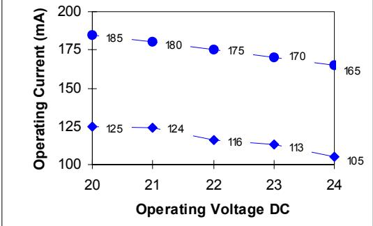
Peak Inrush Current @ 24 Vdc = 7.6 A for less than 50 microseconds.
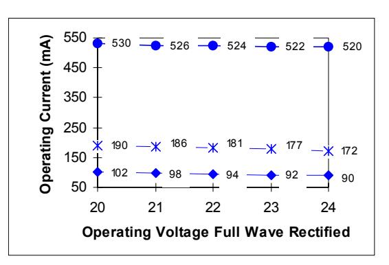
Peak Inrush Current @ 24 Vdc = 6.8 A for less than 50 microseconds.
110 cd Model
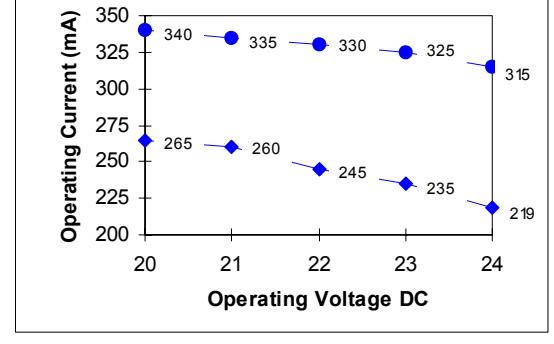
Peak Inrush Current @ 24 Vdc = 7.8 A for less than 50 microseconds.
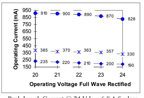
Peak Inrush Current @ 24 Vdc = 6.8 A for less than 50 microseconds.
NOTE: Use the average current rating to establish the maximum number of strobes, wire gauge and standby power requirements. Consult the manufacturer to determine the peak current effects on the system.
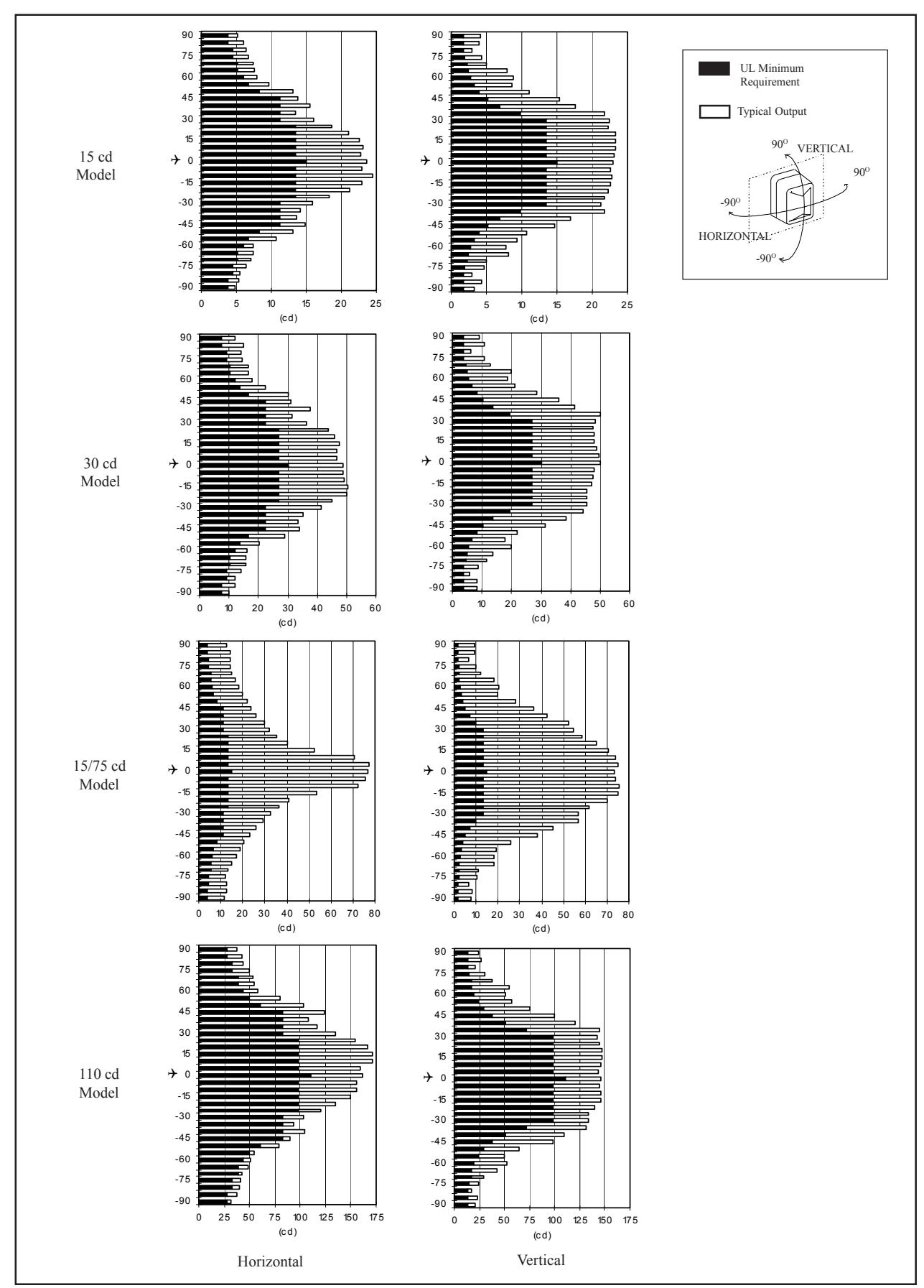
Figure 4. Strobe Light Output Distribution Patterns
P-047550-1720 OFFSET SPEC
STROBE ADAPTER PLATES INSTALLATION INSTRUCTIONS FOR BELL/
PART NUMBER ON THE OUTSIDE. THREE TIMES TO DIMENSIONS SHOWN WITH (1) 11" X 17" SHEET PRINTED BOTH SIDES. FOLD
MATERIAL: STANDARD WHITE OFFSET STOCK
GROUND CHARACTERS: TO BE BLACK ON WHITE BACK-
REDUCED TO ACTUAL SIZE. NOTE: MECHANICALS HAVE ALREADY BEEN
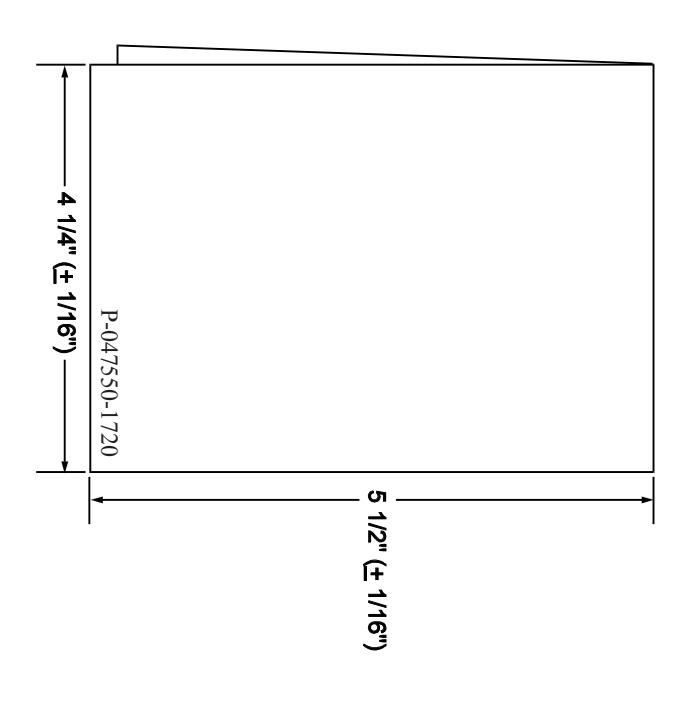
FOLD DETAIL REFERENCE ONLY