Edwards Signaling 2447T Integrity Temporal Horn Installation Sheet
Open the original PDF document
View PDF

Integrity Temporal Horn Installation Sheet
Description
The Integrity Temporal Horn is a fire alarm notification appliance designed for indoor or outdoor walls and ceilings. See Table 1 for temporal horn model numbers and Table 2 for accessory model numbers.
Table 1: Models
| Description | Numbers | |
|---|---|---|
| Temporal horn, red |
757-1A-T
XLS757-1A-T |
INT-T
2447TH-R |
| Temporal horn, white |
757-1A-TW
XLS757-1A-TW |
INT-TW
2447TH-W |
Table 2: Accessories
| Description | Numbers | |
|---|---|---|
| Surface box, red, indoor |
757A-SB
XLS757A-SB |
INT-SB
2459-SMB-R |
| Surface box, white, indoor |
757A-SBW
XLS757A-SBW |
INT-SBW
2459-SMB-W |
|
Weatherproof box, red,
outdoor |
757A-WB
XLS757A-WB |
INT-WB
2459-WPB-R |
|
Weatherproof box, white,
outdoor |
757A-WBW
XLS757A-WBW |
INT-WBW
2459-WPB-W |
|
Bi-directional mounting
frame, red, indoor |
757A-BDF
XLS757A-BDF |
INT-BDF |
|
Bi-directional mounting
frame, white, indoor |
757A-BDFW
XLS757A-BDFW |
INT-BDFW |
Installation
WARNING: Electrocution hazard. To avoid personal injury or death from electrocution, remove all sources of power and allow stored energy to discharge before installing or removing equipment.
Note: Electrical supervision requires the wire run to be broken at each terminal. Do not loop the signaling circuit field wires around the terminals.
Install this product in accordance with applicable requirements in the latest editions of NFPA 72 National Fire Alarm and Signaling Code, CSA C22.1 the Canadian Electrical Code, Part 1, Section 32, CAN/ULC-S524 Installation of Fire Alarm Systems, and in accordance with the local authority having jurisdiction.
To install the temporal horn:
-
1. Select and install a suitable electrical box. See "Mounting the electrical box" on page 2 for details.
- Note: Outdoor installations require a weatherproof backbox.
- 2. Set the tone and pattern. See "Selecting the volume and pattern" on page 2 for details.
- 3. Bring the signal circuit field wiring into the electrical box.
- 4. Position the mounting plate on the electrical box with the hook flange up and facing outward as shown in Figure 2. Fasten the plate using the screws provided.
-
5. Connect the signal circuit field wiring. For the unit to function properly, observe polarity. See Figure 1.
- For additional wiring details, see the installation instructions for the signaling modules or circuits used in the fire alarm control panel.
-
6. After completing the connections, attach the unit to the mounting plate, as noted below.
- a. The grille has tabs (at the top of the inner face) that engage with the hook flange on the mounting plate. Angle the bottom of the grille out slightly, and then slide the unit into place so that the tabs engage the flange.
- b. Seat the grille by pressing the bottom in.
- c. Fasten the bottom of the grille to the mounting plate by tightening the captive locking screw.
- 7. Apply power and activate the unit to verify that it is operating properly.
Figure 1: Typical wiring diagram
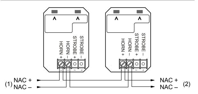
Polarity is shown in the active state.
- (1) From UL/ULC Listed fire alarm control panel signal circuit.
- (2) To next device or end of line resistor for Class B. Return to control panel for Class A connection.
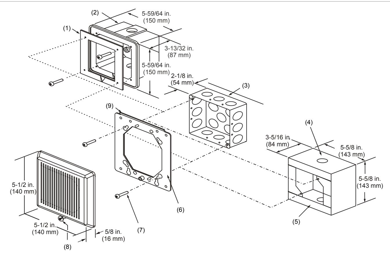
- (1) Gasket with adhesive backing
- (2) Weatherproof box
- (3) Standard box
- (4) Knockouts for 1/2 in. (13 mm) or 3/4 in. (19 mm) conduit top, bottom, back
- Mounting the electrical box
Figure 2 shows mounting details for:
- Standard box. When using a 4 in. square box, use an extension ring for additional wiring space, if needed. If using a double-gang electrical box that is 2-1/2 in. (64 mm) deep, locate the conduit only at the rear of the box.
- Weatherproof box. Peel off the adhesive backing from the gasket and adhere to the box.
- Surface mount box.
Selecting the volume and pattern
The horn has a jumper for selecting a high or low volume output level. The default is high volume. To set the output to low volume, remove the output jumper from the circuit board on the rear of the unit. See Figure 3.
The horn has a jumper for selecting either a temporal or steady tone. The default is temporal tone. To set the output to steady tone, remove the tone jumper from the circuit board on the rear of the unit. See Figure 3.
Tip: Save the jumper by sliding it onto a single pin.
-
(5) Surface mount box
- (6) Mounting plate (supplied with horn)
- (7) #8-32 screw
- (8) Captive locking screw
- (9) Hook flange
Figure 3: Jumper setup and terminal block
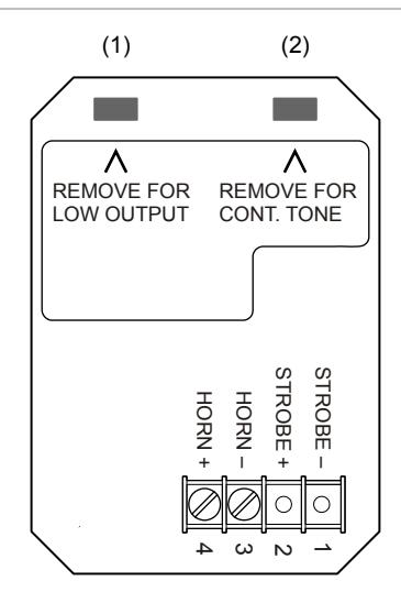
| Item | In | Out |
|---|---|---|
| (1) | High output | Low output |
| (2) | Temporal tone | Continuous tone |
Maintenance
Note: Do not change the factory-applied finishes.
This unit is not serviceable or repairable. Should the unit fail to operate, contact the supplier for replacement.
Perform a visual inspection and an operational test twice a year or as directed by the local authority having jurisdiction.
Specifications
| Operating voltage | 16 to 33 VDC; 16 to 33 VFWR |
|---|---|
| Operating current | |
| 16 to 33 VDC | 85 mA |
| 16 to 33 VFWR | 105 mA |
| Sound output | See Table 3 and Table 4 |
| Synchronization |
Pulses at temporal rate within 200 ms on
common circuit for 30 minutes |
| Horn temporal pattern |
0.5 s on, 0.5 s off, 0.5 s on, 0.5 s off, 0.5 s
on, 1.5 s off, repeat cycle |
| Wire size | 12 to 18 AWG (0.75 to 2.50 mm²) |
|
Compatible electrical
boxes |
2-1/2 in.(64 mm) deep double-gang;
Standard 4 in. square box 2-1/8 in. (54 mm) deep; surface or weatherproof mounting box per Table 1 |
| Operating temperature | |
| Indoor | 32 to 120°F (0 to 49°C) |
| UL outdoor | −31 to 150°F (−35 to 66°C) |
| ULC outdoor | −40 to 150°F (−40 to 66°C) |
| Relative humidity | |
| Indoor | 93% noncondensing |
| Outdoor | 98% noncondensing |
Table 3: Reverberant room sound output (dBA) [1]
| Method | Temporal | Continuous | |||
|---|---|---|---|---|---|
| Low | High | Low | High | ||
| UL464 at 16 VDC | 73 | 80 | 77 | 83 | |
| ULI at 24 VDC | 77 | 83 | 82 | 86 | |
| ULI at 33 VDC | 78 | 85 | 82 | 88 | |
[1] Sound level output at 10 ft. (3.05 m)
Table 4: ULC anechoic room sound output (dBA) [1]
| Method | Temporal | Continuous | |||
|---|---|---|---|---|---|
| Low | High | Low | High | ||
| 16 to 33 VDC | 93 | 98 | 86 | 91 | |
| 16 to 33 VFWR | 96 | 100 | 90 | 93 | |
[1] Average peak sound level output at 10 ft. (3.05 m)
Meets or exceeds CAN/ULC-S525-07, 85 dBA minimum anechoic at 3 meters, all settings
Table 5: ULC directional characteristic
| Angle | dBA | |
|---|---|---|
| 90° | 0 (ref) | |
| 57° and 123° | −3 | |
| 37° and 143° | −6 |
Note: Horizontal and vertical axes provide the same pattern.
Regulatory information
| Manufacturer |
Edwards, A Division of UTC Fire & Security
Americas Corporation, Inc. 8985 Town Center Parkway, Bradenton, FL 34202, USA |
|
Year of
manufacture |
The first two digits of the date code (located on
the product identification label) are the year of manufacture. |
| UL/ULC rating | Regulated 24 DC and Regulated 24 FWR [1] |
|
Environmental
class |
Indoor or outdoor |
|
North American
standards |
Meets: UL 464 and CAN/ULC-S525-07 |
| Follow: NFPA 72 and CAN/ULC-S524 | |
|
2002/96/EC (WEEE directive): Products marked
with this symbol cannot be disposed of as unsorted municipal waste in the European Union. For proper recycling, return this product to your local supplier upon the purchase of equivalent new equipment, or dispose of it at designated collection points. For more information see: www.recyclethis.info. |
[1] This device was tested to the regulated 24 DC/FWR operating voltage limits of 16 V and 33 V.
Contact information
For contact information, see www.utcfireandsecurity.com.