Edwards Signaling 2315 2317 Installation Instruction
Open the original PDF document
View PDF


2315 Series
Panel Door Magnetic Contact
Models: 2315A, 2317A
Installation Instructions
Mounting
Caution: Locate the magnet away from manual handles and latches to prevent it from being used as a foothold or handle to close the door.
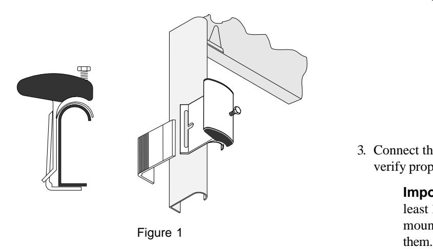
1. Slide the slot of the switch over the beveled-edge of the L-bracket and snap it tightly into place as shown in Figure 1. Screw down firmly.
2. Align the magnet with the switch and use screws to attach it to the door as shown in Figure 2. The switch and magnet must be aligned within 1/2 inch of each
other to prevent false alarms.
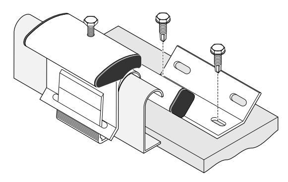
Figure 2
Optional: Use the existing roller-track bolts to mount the switch without using the L-Bracket as shown in Figure 3.
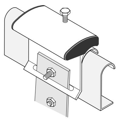
Figure 3
3. Connect the switch wires to the alarm system and test to verify proper operation.
Important: The contact should be mounted at least 13 inches from the floor. If other trackmounted devices interfere, mount the switch under
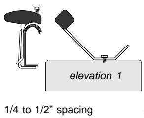
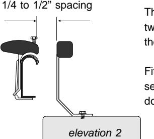
The magnet can be attached at two different elevations from the door.
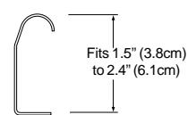
Fits standard 2" roller-tracks for sectional/panel overhead doors.
Figure 4
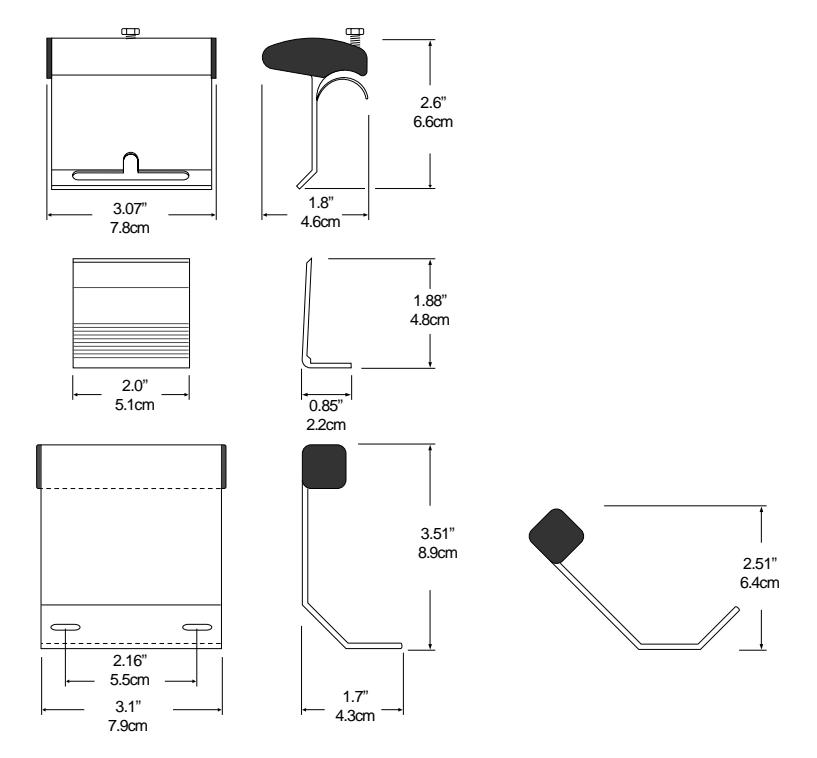
Dimensions
Specifications
General
The contact shall be a hermetically sealed reed switch nominally 3.07" H x 1.80" W x 2.60" D with actuating magnet. Contact and magnet shall be in extruded aluminum type housing. Contact shall be sealed in GE Interlogix exclusive polyurethane potting compound. Mounting bracket shall be furnished with contact. Contacts shall be specified as GE Interlogix part numbers 2315A and 2317A. Contact is designed for installation on metal overhead door tracks.
USA Specifications
Form A (2315A)
Voltage 100V AC/DC max. Current 0.5 A max. Power 7.5 W max.
Form C (2317A)
Voltage 30V AC/DC max. Current 0.25 A max. Power 3.0 W max.
Canadian Specifications
Form A (2315A), Form C (2317A) Voltage 30VDC max. Current 50mA max.
European Union Specifications
Form A (2315A)
Voltage 48V AC/DC max. Current 0.5A max.
WARNING: Each electrical rating is an individual maximum and cannot be
exceeded!
Lead Functions
Form C (2317A)
| Lead Color | Function | |
|---|---|---|
| Black | Common | |
| White | Closed Loop (N.O.) | |
| Red | Open Loop (N.C.) | |
Ordering Information
|
Model
Number |
Loop Type |
Electrical
Configuration |
Gap Distance
(Make)* |
Lead Type | Listing |
|---|---|---|---|---|---|
| 2315A-L | Closed | NO | Up to 3" | 2' stainless steel armored cable | C UL-US |
| 2317A-L | Open or closed | SPDT | Up to 3" | 2' stainless steel armored cable | C UL-US |
* Gap distances are nominal make distance . Gap specifications are for switch to make. Break distance is approximately 1.1 to 1.5 times make.

GE Interlogix
www.GE-InterlogixSecurity.com
12345 SW Leveton Drive Tualatin, OR 97062
USA & Canada: 800-336-4206 Technical Service: 800-454-2363
2266 Second Street North North St. Paul, MN 55109 Phone: 651-777-2690
1030554 Rev B 09/03 Made in Taiwan