Edwards Signaling 200 Series Testing & Wiring Instructions 2013
Open the original PDF document
View PDFSeries 200 Safety Switches
Testing & Wiring Instructions
Wiring for one FailSafe GuardSwitch™
Figure 2
Add a 1/2 amp fast-acting fuse* in series to protect the switch from premature failure caused by inrush-currents, tampering, or excessive vibration.
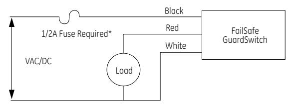
* Use fast-acting Littlefuse 216, fast-acting Microfuse or fast-acting Pico II fuse up to 1/2 Amp.
Wiring for two to ten FailSafe GuardSwitches™ in series
Figure 3
Add a 1/2 amp fast-acting fuse in series to protect the switch from premature failure caused by inrush-currents, tampering, or excessive vibration.
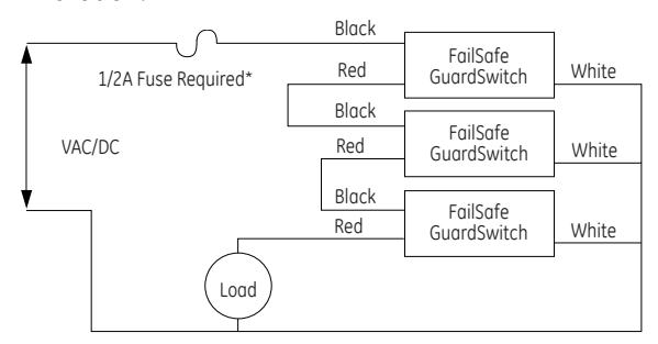
* Use fast-acting Littlefuse 216, fast-acting Microfuse or fast-acting Pico II fuse up to 1/2 Amp.
Testing
After mounting the switch and actuator, test the switch for proper operation. Test with circuit disconnected from source and load. For multiple switches in series, test one switch at a time with all other guard doors closed. Then:
- 1. Hook the black and white leads of the switch to an Ohmmeter. Move the gate or door open and closed several times slowly. At all times the meter should read O.L. or "open."
- 2. Hook the Ohmmeter to the black and red leads of the switch. Move the door or gate open and closed. The meters should read O.L. when the actuator is away and it should read less than 1 Ohm when the actuator is in range.
- 3. Hook the Ohmmeter to the white and red leads of the switch. Move the door or gate open and closed. The meter should read 500-100 ohms when the actuator is away and it should read O.L. when the actuator is in range.
Wiring
- 1. After the switch and actuator have been mounted and tested, wire the FailSafe GuardSwitch™ as shown in Figure 2.
- 2. For wiring 2 to 10 FailSafe GuardSwitches™ in series, see Figure
- 3. (Do not exceed 10 switches in a series).
- 3. Failure to install in-line fuse voids warranty.
Troubleshooting
If the in-line fuse blows or the GuardSwitch™ remains open:
- 1. Check the application for premature failure caused by inrush-currents, tampering, excessive vibration and misalignment.
- 2. Disconnect all three wires of GuardSwitch™ and test according to testing instructions, steps 1-3.
- 3. If the GuardSwitch™ fails any of the three tests, it must be replaced.
- 4. Replace the in-line fuse if blown.
|
Accessories
Accessories |
|
|---|---|
| Part Number | Tamper proof screws & screwdriver |
| 1953 | #6 x 3/4"L Tampruf Roundhead Screw |
| 1954 | #8 x 1-1/2"L Tampruf Roundhead Screw |
| 1955 | Tampruf® Screwdriver |