Edwards Signaling 191 Series Installation Instructions 2013
Open the original PDF document
View PDFZZZHGZDUGVVLJQDOLQJFRP
Warning! To avoid switch failure determine the actual load of the switch circuit and take steps to protect the switch from voltage spikes, current inrush and line/load capacitance using the following recommendations.
- Surges from coils, motors, contactors, solenoids and tungsten filaments. Transient protection, such as back-to-back zener diodes (Transorb) or an RC network, is recommended for such loads to ensure that maximum ratings of the switch are not exceeded.
- Line capacitance and load capacitance. An in-line resistor can be added in series immediately before the load to limit the inrush current. The resistor can only be added in series with the last wire just before the load. The voltage drop and the power rating of the resistor must also be calculated as follows:
Voltage drop = I • R Watts = I2 • R ( I = maximum continuous current of the load)
To verify switch operation with an ohmmeter:
Set range at 20 mega ohms (switches with triac output, set ohm range at 20 kilo ohms). For a normally open switch, the meter will read a high impedance with the actuator away. It will read very high to infinity range (triac switches will read high kilo ohm to infinity range) with the actuator within sense range. You will see the opposite reading for a normally closed switch.
Mounting Configurations
Figure 2
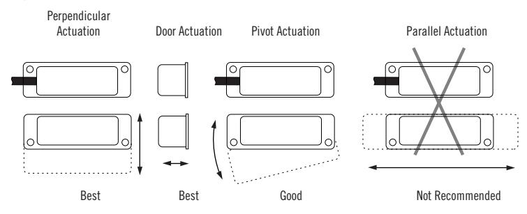
Three configurations are appropriate for interlock applications. The parallel actuation can result in on/off/on signal if the actuator passes by the switch rather than coming to rest in proximity to it. This is NOT a recommended configuration for interlock applications.
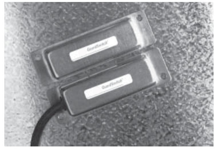
GuardSwitch™ Series 100
Non-Contact Interlock/Position Switch
|
191
193 |
191-3Z-06K
191-3Z-12K 191-4Z-06K 191-4Z-06K-D4 191-4Z-12K 191-4Z-12K-D4 191-6Z-06(K)(A) 191-6Z-12K 191-7Z-06K |
191-7Z-06K-D3
191-7Z-12K 191-7Z-12K-D3 191-8Z-06K 191-8Z-12K 191-17Z-06K 191-17Z-06K-D3 191-17Z-12K 191- |
|---|---|---|
|
193- |
Installation
Use non-removable screws, bolts, or nuts to mount the switch and actuator. Do not over-torque mounting hardware.
-
1. Using the following guidelines, determine a suitable mounting location:
- The switch and actuator must be within the listed sense range. See Ordering/ Electrical Specifications.
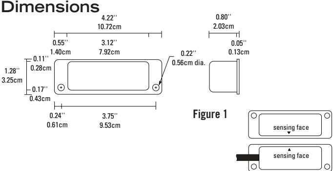
- The actuator must be aligned with the switch—labels facing the same direction. (See Figure 1.)
Important: When mounting in proximity to ferrous material (steel), the sense range can be reduced 50% minimum depending on the shape and type of material. Test the switch in specific applications to determine the actual sense range.
- When mounting on a ferrous material (steel), a 1/4" nonferrous (plastic or aluminum) spacer may be used under the actuator and switch to restore most of the lost gap.
- When mounting on a hinged gate or door, mount the switch and actuator at least 6" away from the hinges to achieve the maximum movement.
- The switch and actuator must move in one of the approved directions. See Figure 2.
- The actuator can be mounted at a 90° rotation to the switch.
- Do not mount for parallel actuation. An on-off-on signal may result when the actuator passes by the switch.
- 2. Mount the switch on the stationary frame of the machine and connect the electrical wiring. When mounting the switch on an ungrounded machine, connect the ground lead to one of the mounting screws.
- 3. Mount the actuator on the movable guard, door, or gate.
Wire Color Codes
| SPDT | Black = Common | |
|---|---|---|
| White = N.O. | ||
| Red = N.C. | ||
| DPST | Circuit 1 | Black, White |
| Circuit 2 | Red, Blue | |
| DPDT | Circuit 1 | Black = Common |
| White = N.O. | ||
| Red = N.C. | ||
| Circuit 2 | Blue = Common | |
| Yellow = N.O. | ||
| Orange = N.C | ||
General Specifications
| Enclosure | Seamless 304 Stainless Steel | |||
| Temperature Range | -40°F to 180°F (-40°C to 80°C) | |||
| Environmental | Hermetically Sealed Contact Switch | |||
| Sealed in Polyurethane | ||||
| NEMA Rating | 1, 2, 3, 4, 4X, 5, 6, 12 | |||
| Protection Class | IP 67 | |||
| Response Time | 1 msec; 10msec (150VA) | |||
| Life Cycles | 100,000 Under Full Load; | |||
| Up to 200,000,000 Under Dry Circuit | ||||
| Lead Types/O.D. | 18/2 SJTOW (K) / 0.30" (0.76cm) | |||
| 18/3 SJTOW (K) / 0.33" (0.84cm) | ||||
| 18/4 SJTOW (K) / 0.34" (0.86cm) | ||||
| 3/16 Armored (A) Stainless Steel Cable with Wire Leads | ||||
| 18GA/0.07" (0.18cm) ea cm | ||||
| UL/CSA | All Models | |||


Ordering/Electrical Specifications
| PART NUMBER 1 |
CONTACT
2
Config. |
LOAD RATING
AC/DC |
SWITCHING VO
Maximum AC/E |
SWITCHING CU
Maximum Ac/ |
CONTACT
Resistence |
SENSE RANGE³
Nominal |
BREAK RANGE
Nominal |
LEAD LENGTH
Nominal |
||
|---|---|---|---|---|---|---|---|---|---|---|
| 191-3Z-06K | N.C. | 100VA/84W | 120V@0.8A | 28V@3.0A4 | 3.0A4@34V | 3.0 A4@28V | 1.0 Ohms | 0.5"(1.3cm) | 1.8"(4.6cm) | 6'(1.8m) |
| 191-3Z-12K | N.C. | 100VA/84W | 120V@0.8A | 28V@3.0A4 | 3.0A4@34V | 3.0A4@28V | 1.0 Ohms | 0.5"(1.3cm) | 1.8"(4.6cm) | 12'(3.6m) |
| 191-4Z-06K | SPDT | 100VA/84W | 120V@0.8A | 28V@3.0A4 | 3.0A4@34V | 3.0A4@28V | 1.0 Ohms | 0.5"(1.3cm) | 1.8"(4.6cm) | 6'(1.8m) |
| 191-4Z-06K-D4 | DPDT; 2SPDT | 100VA/84W | 120V@0.8A | 28V@3.0A4 | 3.0A4@34V | 3.0A4@28V | 1.0 Ohms | 0.5"(1.3cm) | 1.8"(4.6cm) | 2@6'(1.8m) |
| 191-4Z-12K | SPDT | 100VA/84W | 120V@0.8A | 28V@3.0A4 | 3.0A4@34V | 3.0A4@28V | 1.0 Ohms | 0.5"(1.3cm) | 1.8"(4.6cm) | 12'(3.6m) |
| 191-4Z-12K-D4 | DPDT; 2 SPDT | 100VA/84W | 120V@0.8A | 28V@3.0A4 | 3.0A4@34V | 3.0A4@28V | 1.0 Ohms | 0.5"(1.3cm) | 1.8"(4.6cm) | 2@12'(3.6m) |
| 191-6Z-06(K)(A) | N.O. | 25VA/25W | 120V@0.2A | 120V@0.2A | 0.7A@35V | 1.0 A@25V | 0.2 Ohms | 1.0"(2.5cm) | 2.0"(5.1cm) | 6'(1.8m) |
| 191-6Z-12K | N.O. | 25VA/25W | 120V@0.2A | 120V@0.2A | 0.7A@35V | 1.0A@25V | 0.2 Ohms | 1.0"(2.5cm) | 2.0"(5.1cm) | 12'(3.6m) |
| 191-7Z-06K | N.O. | 100VA/84W | 120V@0.8A | 28V@3.0A4 | 3.0A4@34V | 3.0A4@28V | 1.0 Ohms | 0.5"(1.3cm) | 1.8"(4.6cm) | 6'(1.8m) |
| 191-7Z-06K-D3 | DPST 6 N.O./N.C. | 100VA/84W | 120V@0.8A | 28V@3.0A4 | 3.0A4@34V | 3.0A4@28V | 1.0 Ohms | 0.5"(1.3cm) | 1.8"(4.6cm) | 6'(1.8m) |
| 191-7Z-12K | N.O. | 100VA/84W | 120V@0.8A | 28V@3.0A4 | 3.0A4 @34V | 3.0A4@28V | 1.0 Ohms | 0.5"(1.3cm) | 1.8"(4.6cm) | 12'(3.6m) |
| 191-7Z-12K-D3 | DPST N.O./N.C. | 100VA/84W | 120V@0.8A | 28V@3.0A4 | 3.0A4 @34V | 3.0A4@28V | 1.0 Ohms | 0.5"(1.3cm) | 1.8"(4.6cm) | 12'(3.6m) |
| 191-8Z-06K 7 |
N.O./ triac
output |
150VA/NA | 120V@1.25A | NA | 1.25A@120V 5 | NA | NA | 1.0"(2.5cm) | 2.1"(5.3cm) | 6'(1.8m) |
| 191-8Z-12K 7 |
N.O./ triac
output |
150VA/NA | 120V@1.25A | NA | 1.25A@120V 5 | NA | NA | 1.0"(2.5cm) | 2.1"(5.3cm) | 12'(3.6m) |
| 191-17Z-06K | N.O. | 100VA/100W | 250V@0.4A | 250V@0.4A | 3.0A@34V 4 | 3.0A@34V 4 | 0.5 Ohms | 0.5"(1.3cm) | 1.8"(4.6cm) | 6'(1.8m) |
| 191-17Z-06K-D3 | DPST N.O./N.C. | 100VA/100W | 250V@0.4A | 250V@0.4A | 3.0A4 @34V | 3.0A4 @34V | 0.5 Ohms | 0.5"(1.3cm) | 1.8"(4.6cm) | 6'(1.8m) |
| 191-17Z-12K | N.O. | 100VA/100W | 250V@0.4A | 250V@0.4A | 3.0A@34V 4 | 3.0A@34V 4 | 0.5 Ohms | 0.5"(1.3cm) | 1.8"(4.6cm) | 12'(3.6m) |
| 190-Z | Actuator Only | Included with all switches unless otherwise noted. | ||||||||
Warning— Each electrical rating is an individual maximum and cannot be exceeded!
- 1 The part number 193 is the same as 191 in all respects except the cable exits 191 left and 193 right.
- Proximity of ferrous materials usually reduces sense range typically by 50%. The shape and type of material cause a wide diversity of effects. Testing is required to determine actual sense range for specific applications.
- Rated at 3.0A for 6,000 cycles only. Other ratings are at 100,000 cycles.
- Can withstand inrush surge up to 4 amps. Voltage Drop 1.5V, minimum switch current 30mA.
- 6 DPST: 1 N.O., 1 N.C.
- 7 Maximum 10 switches in series.