Edwards Signaling 126 GuardSwitch Installation Instructions
Open the original PDF document
View PDF

www.ge-security.com/industrial
Warning! To avoid switch failure determine the actual load of the switch circuit and take steps to protect the switch from voltage spikes, current inrush and line/load capacitance using the following recommendations.
- Surges from coils, motors, contactors, solenoids and tungsten filaments. Transient protection, such as back-to-back zener diodes (Transorb) or an RC network, is recommended for such loads to ensure that maximum ratings of the switch are not exceeded.
- Line capacitance and load capacitance. An in-line resistor can be added in series immediately before the load to limit the inrush current. The resistor can only be added in series with the last wire just before the load. The voltage drop and the power rating of the resistor must also be calculated as follows:
Voltage drop = I • R Watts = I2 • R
( I = maximum continuous current of the load)
To verify switch operation with an ohmmeter:
Set range at 20 mega ohms (switches with triac output, set ohm range at 20 kilo ohms). For a normally open switch, the meter will read a high impedance with the actuator away. It will read very high to infinity range (triac switches will read high kilo ohm to infinity range) with the actuator within sense range. You will see the opposite reading for a normally closed switch.
Dimensions
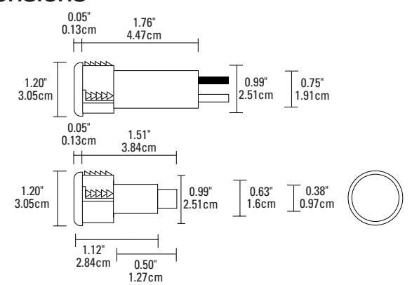
Figure 1
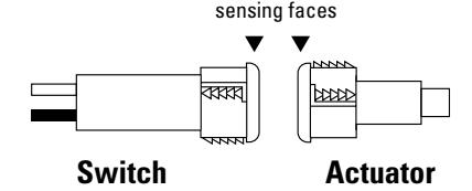
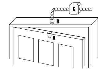
Figure 2
GuardSwitch™ Series 100
Magnetic Door Position Switch
| 126-7Y-01AX |
|---|
| 126-8Y-01AX |
| 126-8Y-06X |
| 126-8Y-03AX |
| 126-EY-03AX |
|
126-
|
Installation
The Model 126 is designed for use with tungsten filament bulbs of 150-watt rating or less at 120 volts.
-
1. Using the following guidelines, determine a suitable mounting location:
- The switch and actuator must be within the listed sense range. See Ordering/ Electrical Specifications.
- The actuator must be aligned with the switch—labels facing the same direction. (See Figure 1.)
Important: When mounting in proximity to ferrous material (steel), the sense range can be reduced 50% minimum depending on the shape and type of material. Test the switch in specific applications to determine the actual sense range.
- 2. Determine location of switch on door jamb. To ensure proper operation and that the magnetic field not interfere with switching, do not locate closer than six inches from hinge side of door.
- 3. Locate switch (B) and magnet (A) locations on door jamb and door. (See Figure 2.) Drill a one-inch hole to accomodate these. (Do not hammer. This can damage the switch.) Misalignment of up to 1/2-inch can be tolerated, but not in a ferrous metal door. (To check if a door or jamb is ferrous hold a magnet to it. If it is attracted it is ferrous.)
- 4. Connect the black line conductor, see Figure 3, to the fuse and fuse holder that are provided. Connect the white neutral conductor to the load. Connect the flexible conduit to a NEMA Type I enclosure, see Figure 2.C, using a properly sized and acceptable 3/8 inch flexible conduit connector. If the switch is being used in a branch circuit, connect to a UL listed relay with minimum rating of 120VAC/15A.
- 5. The switch and actuator must move in one of the approved directions. See Figure 4.
Note: Before making electrical connections be sure that power is off. Electrical connections are black to line and white to load (bulb).
Figure 3
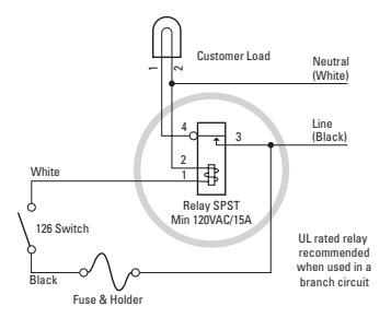
Figure 4 Barrel Switch Mounting Configurations
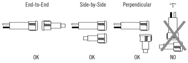
Three configurations are appropriate for recessed interlock applications. Moving the actuator parallel to the switch can result in on/off/on signal if the actuator passes by the switch rather than coming to rest in proximity to it. This is NOT a recommended configuration for interlock/position applications. "T" configuration results in non-actuation.
General Specifications
| Enclosure | ABS Plastic with Protective PVC | |||
|---|---|---|---|---|
| Switch Sleeve | ||||
| Temperature Range | -40°F to 122°F (-40°C to 50°C) | |||
| NEMA Rating | 1, 2, 3, 4, 4X, 5, 6, 12 | |||
| Protection Class | IP 67 | |||
| Response Time | 10 msec | |||
| Life Cycles | 100,000 Under Full Load; | |||
| Up to 200,000,000 Under Dry Circuit | ||||
| Lead Types/O.D. | 12 AWG (AX)/0.13" (0.33cm) | |||
| Flex Conduit (X)/0.58" (1.5cm) | ||||
| UL/CSA Certified | All Models | |||


New York Calendar #40018
Ordering/Electrical Specifications
| PART NUMBER |
CONTACT
1
Config. |
LOAD RATING
AC/DC |
SWITCHING VOLTAGE
Maximum, Ac/DC |
SWITCHING CUP
Maximum, AC/D |
SENSE RANGE
2
Nominal |
BREAK RANGE
Nominal |
LEAD LENGTH | ||||
|---|---|---|---|---|---|---|---|---|---|---|---|
| 126-EY-01AX 4 |
N.C./ triac
output |
150VA/NA | 120V@1.25A | NA | 1.25A³@120V | NA | 1.0"(2.5cm) | 1.5"(3.8cm) | 1'(0.3m) | ||
| 126*-EY-03AX4 |
N.C./ triac
output |
150VA/NA | 120V@1.25A | NA | 1.25A³@120V | NA | 1.0"(2.5cm) | 1.5"(3.8cm) | 3'(0.9m) | ||
| 126*-EY-06AX 4 |
N.C./ triac
output |
150VA/NA | 120V@1.25A | NA | 1.25A 3 @120V | NA | 1.0"(2.5cm) | 1.5"(3.8cm) | 6'(1.8m) | ||
| 126-EY-06X 4 |
N.C./ triac
output |
150VA/NA | 120V@1.25A | NA | 1.25A³@120V | NA | 1.0"(2.5cm) | 1.5"(3.8cm) | 6'(1.8m) | ||
| 126-3Y-01AX | N.C. | 100VA/84W | 120V@0.8A | 28V@3.0A | 3.0A@34V | 3.0A@28V | 0.5"(1.3cm) | 1.0"(2.5cm) | 1'(0.3m) | ||
| 126-4Y-01AX | SPDT | 100VA/84W | 120V@0.8A | 28V@3.0A | 3.0A@34V | 3.0A@28V | 0.5"(1.3cm) | 1.0"(2.5cm) | 1'(0.3m) | ||
| 126-7Y-01AX | N.O. | 100VA/84W | 120V@0.8A | 28V@3.0A | 3.0A@34V | 3.0A@28V | 0.5"(1.3cm) | 1.0"(2.5cm) | 1'(0.3m) | ||
| 126-8Y-01AX 4 |
N.C./ triac
output |
150VA/NA | 120V@1.25A | NA | 1.25A³120V | NA | 0.5"(1.3cm) | 1.0"(2.5cm) | 1'(0.3m) | ||
| 126-8Y-06X 4 |
N.O./ triac
output |
150VA/NA | 120V@1.25A | NA | 1.25A 3 120V | NA | 1.0"(2.5cm) | 1.5"(3.8cm) | 6'(1.8m) | ||
| 126-8Y-03AX 4 |
N.O./ triac
output |
150VA/NA | 120V@1.25A | NA | 1.25A 3 120V | NA | 1.0"(2.5cm) | 1.5"(3.8cm) | 3'(0.9m) | ||
| 126*-EY-03AX4 |
N.C./ triac
output |
150VA/NA | 120V@1.25A | NA | 1.25A 3 120V | NA | 1.0"(2.5cm) | 1.5"(3.8cm) | 3'(0.9m) | ||
| 126-Y | Actuator Only | Included with all switches unless otherwise noted. | |||||||||
Warning— Each electrical rating is an individual maximum and cannot be exceeded!
- 1 Configuration with actuator away from the switch
- 2 Proximity of ferrous materials usually reduces sense range typically by 50%. The shape and type of material cause a wide diversity of effects. Testing is required to determine actual sense range for specific applications.
- Can with stand inrush surge up to 4 Amps. Voltage Drop 1.5V. Minimum switch current 30 mA.
- 4 Maximum 25 switches in series.

www.ge-security.com/industrial
12345 SW Leveton Drive Tualatin, OR 97062 Phone: 800-247-9447 Fax: 503-691-7563