Edwards Signaling 125XBR LED Instructions
Open the original PDF document
View PDF

Installation Instructions for 125 Class Beacons, XBR (XTRA-BRIGHT) LED Models
Description
Edwards 125 Class XBR LED Beacons are UL and cUL listed dual mode signaling appliances rated for NEMA 4X applications. Two versions of 125 Class XBR LED Beacons are available: Steady-On/Flashing (125XBR M ) and Steady-On/ Lightburst (125XBR Z ). Both versions can be either surface or conduit mounted. A protective wire guard, Cat. No. 125GRD, is also available.
Both 125XBRM and 125XBRZ beacons are dual mode devices maximizing application flexibility while reducing inventory costs. 125XBRM beacons ship from the factory in Steady-On mode with the built-in option of switching to (65 fpm) Flashing mode by means of an additional wire connection. (Refer to "Setting the Flash Mode" for details). In the same manner, 125XBRZ beacons ship from the factory in Steady-On mode and where ultra visibility is critical, can be easily switched to Lightburst mode. (Refer to "Setting the Flash Mode" for details). 125 Class XBR (XTRA-BRIGHT) LED Beacons are available in red, blue, green, amber, or white.
Electrical Specifications
| GRAY BASE | BLACK BASE | |||
|---|---|---|---|---|
| Catalog Number | Catalog Number | Electrical Specs | Color | |
| Steady-On/Flashing | ||||
| 125XBRMA24D | 125XBRMA24DB | 24V DC, 0.215A | Amber | |
| 125XBRMA120A | 125XBRMA120AB | 120V AC*, 0.108A | Amber | |
| 125XBRMB24D | 125XBRMB24DB | 24V DC, 0.215A | Blue | |
| 125XBRMB120A | 125XBRMB120AB | 120V AC*, 0.108A | Blue | |
| 125XBRMG24D | 125XBRMG24DB | 24V DC, 0.215A | Green | |
| 125XBRMG120A | 125XBRMG120AB | 120V AC*, 0.108A | Green | |
| 125XBRMR24D | 125XBRMR24DB | 24V DC, 0.215A | Red | |
| 125XBRMR120A | 125XBRMR120AB | 120V AC*, 0.108A | Red | |
| 125XBRMW24D | 125XBRMW24DB | 24V DC, 0.215A | White | |
| 125XBRMW120A | 125XBRMW120AB | 120V AC*, 0.108A | White | |
| Steady-On/Lightburst | ||||
| 125XBRZA24D | 125XBRZA24DB | 24V DC, 0.215A | Amber | |
| 125XBRZA120A | 125XBRZA120AB | 120V AC*, 0.108A | Amber | |
| 125XBRZB24D | 125XBRZB24DB | 24V DC, 0.215A | Blue | |
| 125XBRZB120A | 125XBRZB120AB | 120V AC*, 0.108A | Blue | |
| 125XBRZG24D | 125XBRZG24DB | 24V DC, 0.215A | Green | |
| 125XBRZG120A | 125XBRZG120AB | 120V AC*, 0.108A | Green | |
| 125XBRZR24D | 125XBRZR24DB | 24V DC, 0.215A | Red | |
| 125XBRZR120A | 125XBRZR120AB | 120V AC*, 0.108A | Red | |
| 125XBRZW24D | 125XBRZW24DB | 24V DC, 0.215A | White | |
| 125XBRZW120A | 125XBRZW120AB | 120V AC*, 0.108A | White | |
* 120 V AC 50/60 Hz
Mechanical Specifications
Outdoor Locations Temperature Ratings ...........-31F to +150F (-35C to +66C)

WARNING
To prevent electrical shock, ensure that power is turned off before installing the signal.
Installation
Conduit Mounting (Figures 1 & 3)
- 1. Feed the 18" (457 mm) signal wire leads through either 1/2" or 3/4" conduit into an approved conduit outlet box. (Product is supplied with a double threaded - 1/2" internal and 3/4" external - conduit hub.)
- 2. Thread the conduit onto the base of the signal.
Panel Mounting (Figures 2 & 4)
Note: When panel mounting these beacons, the surface and construction details of the panel must be taken into consideration in order to ensure that the integrity of the outdoor, NEMA 4X rating is fully maintained. Installer should evaluate.
- 1. Place the mounting gasket (supplied) over the hole in the panel and route the signal wires through the gasket and the hole in the panel.
- 2. Insert the base through the hole in the panel and screw the locking nut (supplied), with the raised locking edge facing the mounting surface, onto the base to secure the beacon.

WARNING
To avoid risk of injury, install lens before energizing the unit and do not remove or insert light source when unit is energized.
Wiring
-
1. Using wire nuts (not supplied), connect the signal's wire leads as shown in Figure 1 or 2. Polarity must be observed on DC models.
- AC Models: Connect the black wire to hot and the white wire to common.
- DC Models: Connect the red wire to positive (+) and the black wire to negative (-).
2. Turn on power and verify that the signal operates properly.
Changing the Flash Mode
To change the flash mode from Steady-On to Flashing on 125XBRM beacons or from Steady-On to Lightburst on 125XBRZ beacons, connect the optional yellow wire as follows:
- AC Models: Connect yellow wire to hot
- DC Models: Connect yellow wire to positive
NOTE: When using as shipped in Steady-On mode, cap the yellow wire with a wire nut (supplied).
(See Figures 1 - 4 for details.)
Maintenance

WARNING
To avoid risk of injury, install lens before energizing the unit.
To avoid the risk of injury, do not start any maintenance when unit is energized.
Cleaning
Disconnect power before cleaning. The module lens exterior surfaces should be periodically cleaned with a soft clean cloth using water and a mild detergent to maintain optimum light visibility.
Figure 1. Conduit Mounting (3/4" Shown) Figure 2. Panel Mounting
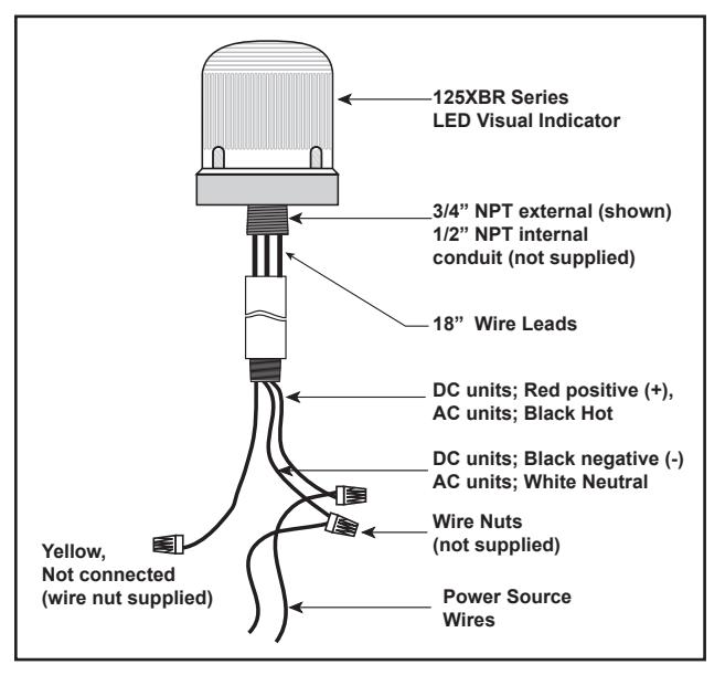
- Wiring for 125XBRM or 125XBRZ Steady-On Mode - Wiring for 125XBRM or 125XBRZ Steady-On Mode
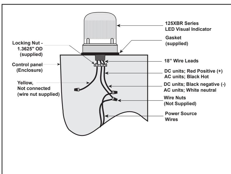
Figure 3. Conduit Mounting (3/4" Shown) Figure 4. Panel Mounting
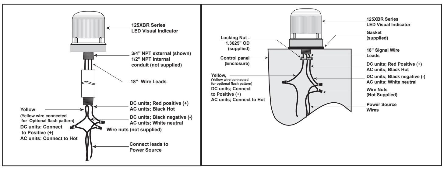
- Wiring for 125XBRM Flashing Mode
- Wiring for 125XBRZ Lightburst Mode
- Wiring for 125XBRM Flashing Mode
- Wiring for 125XBRZ Lightburst Mode
Table 1. Replacement Parts
| GRAY BASE | BLACK BASE | |||
|---|---|---|---|---|
| Catalog Number | Catalog Number |
Replacement
Lens |
Replacement Lamp | |
| Steady-On/65 fpm Flashing LED | ||||
| 125XBRM*24D | 125XBRM*24DB |
The 148,000 hour*** LED light
source is permanently installed. |
||
| 125XBRM*120A | 125XBRM*120AB | 125L** | ||
| Steady-On/Lightburst LED | ||||
| 125XBRZ*24D | 125XBRZ*24DB |
The 148,000 hour*** LED light
source is permanently installed. |
||
| 125XBRZ*120A | 125XBRZ*120AB | 125L** | ||
| *Letter in this position indicates lens/LED color: A - amber, B - blue, G - green, R - red, | ||||
W - white LED's with clear lens
** Lens color: A - amber, B - blue, C - clear, G - green, R - red
** Median LED Life (L70) based on LED manufacturer's projections. Refer to http://www.philipslumileds.com/pdfs/WP15.pdf.

U.S. T 800-336-4206 F 800-454-2363
Canada T 519 376 2430 F 519 376 7258
Asia T 852 2907 8108 F 852 2142 5063
Australia T +61 3 9239 1200 F +61 3 9239 1299
Europe T 32 2 725 11 20 F 32 2 721 86 13
Latin America T 305 593 4301 F 305 593 4300
www.edwardssignaling.com