Edwards Signaling 125 Class Standard LED Instructions
Open the original PDF document
View PDF

Installation Instructions for 125 Class Beacons, STANDARD LED Models
Description
Edwards 125 Class LED Beacons are UL and cUL listed signaling appliances rated for NEMA 4X applications. Two versions of 125 Class Standard LED Beacons are available: Flashing 65 FPM (125LEDF) and Steady-On (125LEDS). Both versions can be either surface or conduit mounted.
A protective wire guard, Cat. No. 125GRD, is available.
Electrical Specifications
| GRAY BASE | BLACK BASE | ||||
|---|---|---|---|---|---|
| Catalog Number | Catalog Number | Voltage | Current | ||
| Flashing LED | |||||
| 125LEDF*24D | 125LEDF*24DB | 24V DC | 0.060A | ||
| 125LEDF*120A | 125LEDF*120AB | 120V AC 50/60 Hz | 0.097A | ||
| Steady-On LED | |||||
| 125LEDS*24D | 125LEDS*24DB | 24V DC | 0.060A | ||
| 125LEDS*120A | 125LEDS*120AB | 120V AC 50/60 Hz | 0.097A | ||
|
*Letter in this position indicates lens/LED color:
A - Amber, B - Blue, G - Green, R - Red |
|||||
Mechanical Specifications
Outdoor Locations Temperature Ratings ...........-31F to +150F (-35C to +66C)
Installation

WARNING
To prevent electrical shock, ensure that power is turned off before installing the signal.
Conduit Mounting (Figure 1)
- 1. Thread the 18" (457 mm) signal wire leads through either 1/2" or 3/4" conduit into an approved conduit outlet box. (Product is supplied with a double threaded - 1/2" internal and 3/4" external - conduit hub.)
-
2. Wire the beacon as follows:
- a. For AC models, use wire nuts (not supplied) and connect the signal's black and white wire leads to the power source wires as shown in Figure 1.
- b. For DC models, connect the signal's red wire to the positive power source wire and connect the signal's black wire to the negative power source wire using wire nuts (not supplied). Polarity must be observed. Refer to Figure 1.
- 3. Thread the conduit onto the base of the signal.
- 4. Turn on power and verify that the signal operates properly.
Panel Mounting (Figure 2)

WARNINGS
To avoid risk of injury, install lens before energizing the unit.
To avoid the risk of injury, do not remove or insert lamp when unit is energized.
Note: When panel mounting the beacon, the surface and construction details of the panel must be taken into consideration in order to ensure that the integrity of the outdoor, NEMA 4X rating is fully maintained. Installer should evaluate.
- 1. Place the mounting gasket (supplied) over the hole in the panel and route the signal wires through the gasket and the hole in the panel.
- 2. Insert the base through the hole in the panel and screw the locking nut (supplied), with the raised locking edge facing the mounting surface, onto the base to secure the beacon.
-
3. Wire the beacon as follows:
- a. For AC models, use wire nuts (not supplied) and connect the signal's black and white wire leads to the power source wires as shown in Figure 2. Polarity is not relevant.
- b. For DC models, connect the signal's red wire to the positive power source wire and connect the signal's black wire to the negative power source wire using wire nuts (not supplied). Polarity must be observed. Refer to Figure 2.
- 4. Turn on power and verify that the signal operates properly.
P/N 3101756 ISSUE 3 © 2010
Maintenance
WARNINGS
To avoid risk of injury, install lens before energizing the unit.
To avoid the risk of injury, do not start any maintenance when unit is energized.
Cleaning
Disconnect power before cleaning. The module lens exterior surfaces should be periodically cleaned with a soft clean cloth using water and a mild detergent to maintain optimum light visibility.
Figure 1. Conduit Mounting (3/4" Shown)
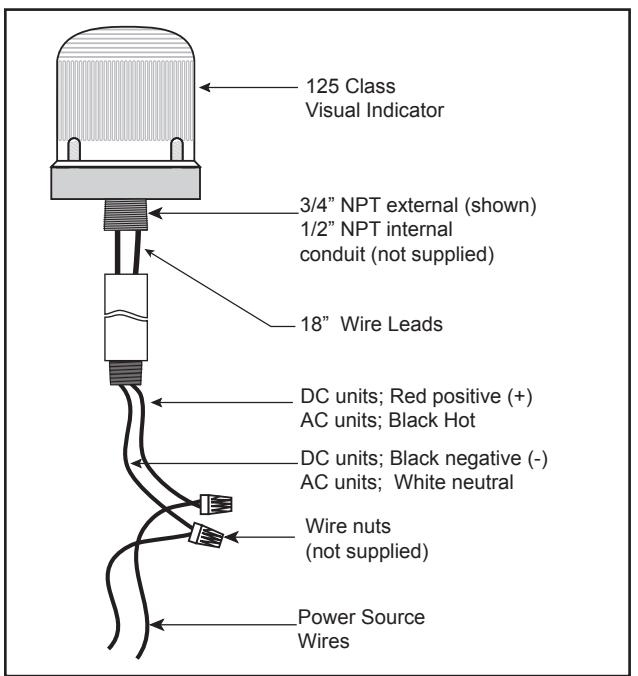
Figure 2. Panel Mounting
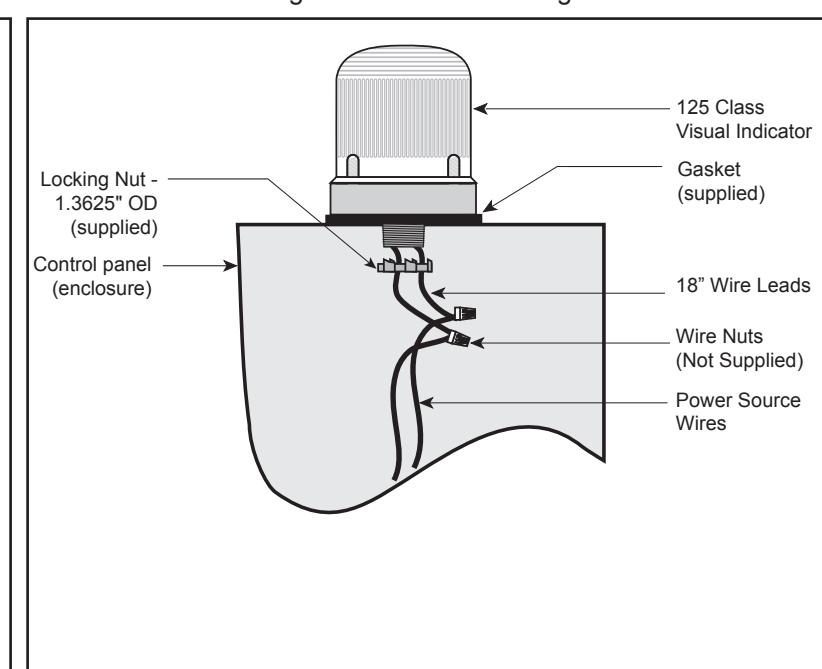
Table 1. Replacement Parts
| GRAY BASE | BLACK BASE | ||||
|---|---|---|---|---|---|
| Catalog Number | Catalog Number |
Replacement
Lens |
Replacement Lamp | ||
| Flashing LED | |||||
| 125LEDF*24D | 125LEDF*24DB | 125L* | The 100,000 hour** LED light source is permanently installed. | ||
| 125LEDF*120A | 125LEDF*120AB | 125L | |||
| Steady-On LED | |||||
| 125LEDS*24D | 125LEDS*24DB | 125L* | The 100,000 hour** LED light | ||
| 125LEDS*120A | 125LEDS*120AB | 125L" | source is permanently installed. | ||
| *Letter in this position indicates lens color: A - Amber, B - Blue, G - Green, R - Red **Based on LED manufacturer's projections. | |||||