Edwards Signaling 125 Class Incand Instructions
Open the original PDF document
View PDF

Installation Instructions for 125 Class Beacons, INCANDESCENT Models
Description
Edwards 125 Class Beacons are UL and cUL listed signaling appliances rated for NEMA 4X applications. Two versions of incandescent beacons are available: Flashing (125INC F ) and Steady-on (125INC S ). Both types can be either surface or conduit mounted.
A protective wire guard, Cat. No. 125GRD, is available.
Electrical Specifications
| GRAY BASE | BLACK BASE | ||||||
|---|---|---|---|---|---|---|---|
| Catalog Number | Catalog Number |
Voltage
Current |
|||||
| Flashing Incandescent | |||||||
| 125INCF*24D | 125INCF*24DB | 24V DC | 0.610A | ||||
| 125INCF*120A | 125INCF*120AB | 120V AC 50/60 Hz | 0.510A | ||||
| Steady-On Incandescent | |||||||
| 125INCS*24D | 125INCS*24DB | 24V DC | 0.610A | ||||
| 125INCS*120A | 125INCS*120AB | 120V AC 50/60 Hz | 0.510A | ||||
|
*Letter in this position designates lens color:
A - amber, B - blue, C - clear, G - green, or R - red |
|||||||
Mechanical Specifications
Outdoor Locations Temperature Ratings ...........-31F to +150F (-35C to +66C)
Installation

WARNING
To prevent electrical shock, ensure that power is turned off before installing the signal.
Conduit Mounting (Figure 1)
- 1. Thread the 18" (45.7 cm) signal wire leads through 1/2" conduit into an approved conduit outlet box.
- 2. Thread the conduit onto the base of the signal.
- 3. Using wire nuts (not supplied), connect the signal's wire leads as shown in Figure 1. Polarity must be observed for DC models. For AC models, polarity is not important.
Panel Mounting (Figure 2)
Note: When panel mounting the beacon, the surface and construction details of the panel must be taken into consideration in order to ensure that the integrity of the outdoor, NEMA 4X rating is fully maintained. Installer should evaluate.
- 1. Place the mounting gasket (supplied) over the hole in the panel and route the signal wires through the gasket and the hole in the panel.
- 2. Insert the base through the hole in the panel and screw the locking nut (supplied), with the raised locking edge facing the mounting surface, onto the base to secure the beacon.
- 3. Using wire nuts (not supplied), connect the signal's wire leads as shown in Figure 2. Polarity must be observed.
Maintenance

WARNINGS
To prevent electrical shock, ensure power is turned off before installation or maintenance.
To avoid risk of injury, install lens before energizing.
Cleaning
To maintain optimum light visibility, the exterior lens surfaces should be periodically cleaned with a soft clean cloth using water and a mild detergent. Disconnect power before cleaning.
Light Source Replacement
1. Conduit Mounted Modules: Disconnect wiring and, if necessary, unscrew base from conduit (Figure 1).
Panel Mounted Modules: Disconnect wiring and remove locking nut that secures the base to the panel (Figure 2).
- 2. Remove screws that secure the lens to the base from bottom of base and remove lens.
- 3. Unplug lamp and replace with appropriate new lamp (as specified in Table 1 - Replacement Parts). Reattach lens to base and fasten with screws removed in step 2.
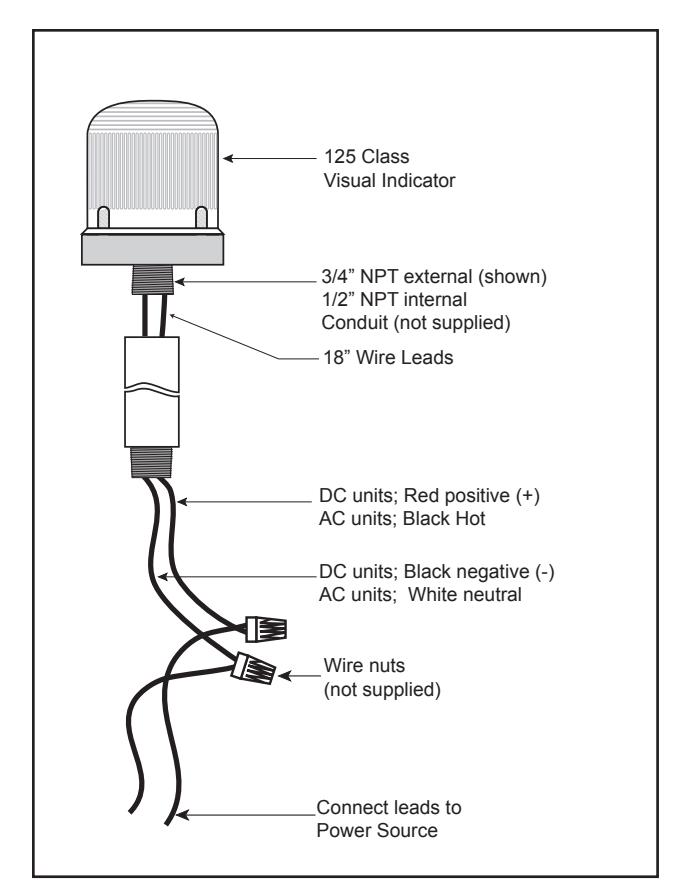
Figure 1. Conduit Mounting (3/4" Shown)
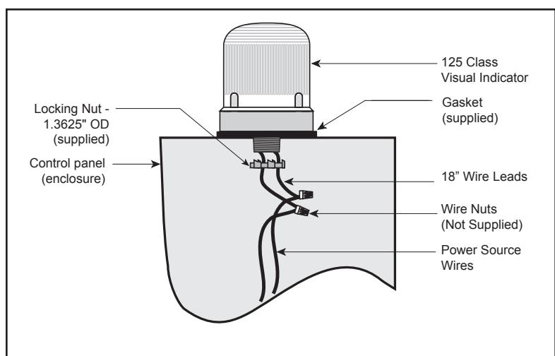
Figure 2. Panel Mounting
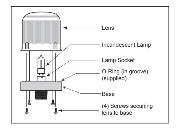
Figure 3. Lamp Replacement
Table 1. Replacement Parts
| Catalog Number (gray base) | Catalog Number (black base) |
Replacement
Lens |
Replacement Lamp | ||||
|---|---|---|---|---|---|---|---|
| Flashing Incandescent | |||||||
| 125INCF*24D | 125INCF*24DB | 125L* | Industry Trade 1692 | ||||
| 125INCF*120A | 125INCF*120AB | 125L | Industry Trade 15T7DC | ||||
| Steady-On Incandescent | |||||||
| 125INCS*24D | 125INCS*24DB | 125L* | Industry Trade 1692 | ||||
| 125INCS*120A | 125INCS*120AB | 123L | Industry Trade 15T7DC | ||||
| *Letter in this position indicates lens color: A - Amber, B - Blue, C - Clear, G - Green, R - Red. | |||||||
Table 2. Programming Logic Controller (PLC) Compatibility: PLC Output to meet following product input parameters
| Cat. No.* | Operating voltage (Volts) |
Max. off state leak-
age current (mA) |
Continuous on current (mA) |
Repetitive
Surge |
Surge
(inrush/duration) |
||
|---|---|---|---|---|---|---|---|
| 125INCF24D | 24V DC | 25 | 25 | 0.68A | 7A exp decaying | ||
| 125INCF120A | 120V AC 50/60 Hz | 25 | 25 | 0.3A / 8 ms | 0.8A exp decaying | ||
| 125INCS24D | 24V DC | 25 | 25 | 2.5A / 60 ms | 7A exp decaying | ||
| 125INCS120A | 120V AC 50/60 Hz | 25 | 25 | 0.5A / 8 ms | 0.8A exp decaying | ||
| *PLC compatibility applies to models with any lens color and with either a gray or black base. | |||||||