Edwards Signaling 125 Class Halogen Installation Instructions
Open the original PDF document
View PDF

Installation Instructions for 125 Class Beacons, HALOGEN Models
Description
Edwards 125 Class halogen beacons are UL and cUL listed signaling appliances rated for NEMA 4X applications. Two versions of 125 Class Halogen Beacons are available: Flashing (125HAL F ) and Steady-On (125HAL S ). Both versions can be either surface or conduit mounted.
A protective wire guard, Cat. No. 125GRD, is available.
Electrical Specifications
| GRAY BASE | BLACK BASE | ||
|---|---|---|---|
| Catalog Number | Catalog Number | Voltage | Current |
| Flashing Halogen | |||
| 125HALF*24D | 125HALF*24DB | 24V DC | 0.770A |
| 125HALF*24A | 125HALF*24AB | 24V AC 50/60 Hz | 0.770A |
| 125HALF*120A | 125HALF*120AB | 120V AC 50/60 Hz | 0.200A |
| Steady-On Halogen | |||
| 125HALS*24D | 125HALS*24DB | 24V DC | 0.770A |
| 125HALS*24A | 125HALS*24AB | 24V AC 50/60 Hz | 0.770A |
| 125HALS*120A | 125HALS*120AB | 120V AC 50/60 Hz | 0.200A |
|
*Letter in this position indicates lens color:
A - Amber, B - Blue, C - Clear, G - Green, R - Red |
|||
Mechanical Specifications
Outdoor Locations Temperature Ratings ...........-31F to +150F (-35C to +66C)
Installation

WARNING
To prevent electrical shock, ensure that power is turned off before installing the signal.
Conduit Mounting (Figure 1)
1. Thread the 18" (45.7 cm) signal wire leads through either 1/2" or 3/4" conduit into an approved conduit outlet box. (Product is supplied with a double threaded - 1/2" internal and 3/4" external - conduit hub.)
-
2. Wire the beacon as follows:
- a. For AC models, use wire nuts (not supplied) and connect the signal's black and white wire leads to the power source wires as shown in Figure 1. Polarity is not relevant.
- b. For DC models, connect the signal's red wire to the positive power source wire and connect the signal's black wire to the negative power source wire using wire nuts (not supplied). Polarity must be observed. Refer to Figure 1.
- 3. Thread the conduit onto the base of the signal.

WARNINGS
To avoid risk of injury, install lens before energizing the unit.
To avoid the risk of injury, do not remove or insert lamp when unit is energized.
4. Turn on power and verify that the signal operates properly.
Panel Mounting (Figure 2)
Note: When panel mounting the beacon, the surface and construction details of the panel must be taken into consideration in order to ensure that the integrity of the outdoor, NEMA 4X rating is fully maintained. Installer should evaluate.
- 1. Place the mounting gasket (supplied) over the hole in the panel and route the signal wires through the gasket and the hole in the panel.
- 2. Insert the base through the hole in the panel and screw the locking nut (supplied), with the raised locking edge facing the mounting surface, onto the base to secure the beacon.
-
3. Wire the beacon as follows:
- a. For AC models, use wire nuts (not supplied) and connect the signal's black and white wire leads to the power source wires as shown in Figure 2. Polarity is not relevant.
- b. For DC models, connect the signal's red wire to the positive power source wire and connect the signal's black wire to the negative power source wire using wire nuts (not supplied). Polarity must be observed. Refer to Figure 2.
- 4. Turn on power and verify that the signal operates properly.
P/N 3101650 ISSUE 3

WARNINGS
To avoid risk of injury, install lens before energizing the unit.
To avoid the risk of injury, do not start any maintenance when unit is energized.
To prevent electrical shock, disconnect all power and wait five (5) minutes for stored energy in strobe modules to dissipate before starting work on unit.
Cleaning
Disconnect power before cleaning. The module lens exterior surfaces should be periodically cleaned with a soft clean cloth using water and a mild detergent to maintain optimum light visibility.
Lamp Replacement
Conduit Mounted Modules: Disconnect wiring and, if necessary, unscrew base from conduit (Figure 1).
Panel Mounted Modules: Disconnect wiring and remove locking nut that secures the base to the panel (Figure 2).
- 2. Remove (4) screws that secure the lens to the base from bottom of base (Figure 3) and remove lens.
-
3. Replace halogen lamp as follows (Figure 3):
- Grasp the metal base of the halogen lamp and push the lamp down while turning counterclockwise. Then, pull the lamp directly upward to remove from the socket.
- Grasp the new halogen lamp by its base and insert in the socket. Push down and rotate clockwise to lock in place.
CAUTION: Do not touch glass surface of lamp at any time.)
4. Reattach lens to base and fasten with screws removed in step 2.
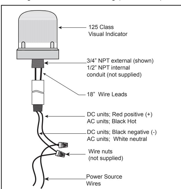
Figure 1. Conduit Mounting (3/4" Shown)

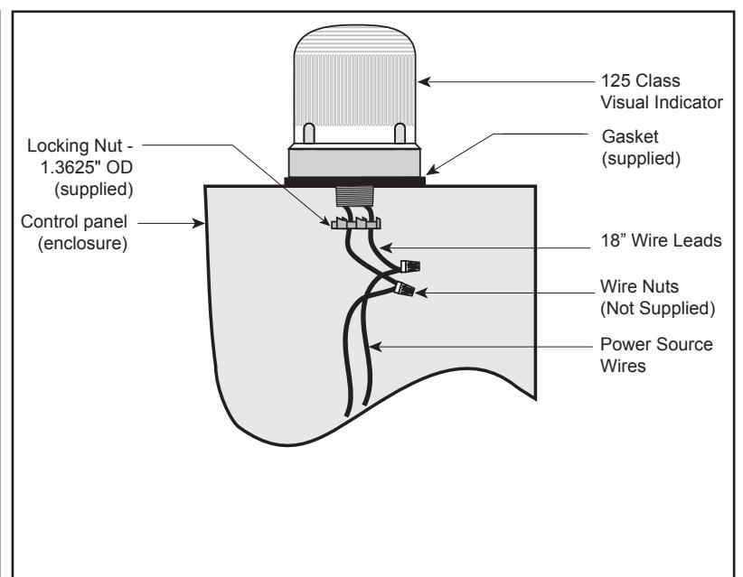
Figure 3. Lamp Replacement
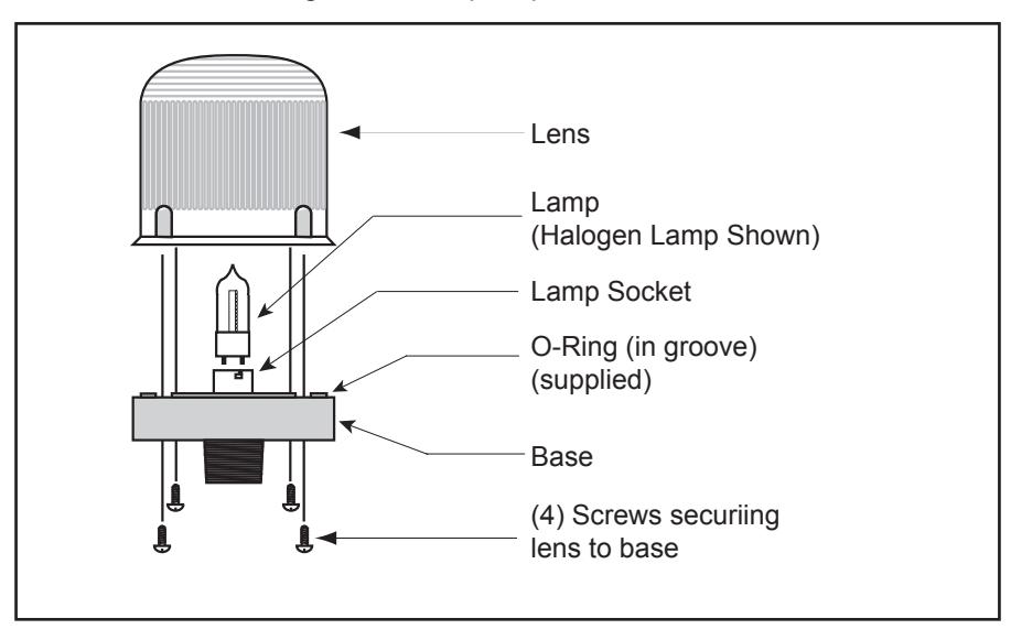
Table 1. Replacement Parts
|
50LMP-9WH-D or industry trade
no. 1692** (incandescent) 50LMP-12WH-D or industry trade |
|---|
| no. 15T7DC** (incandescent) |
|
50LMP-9WH-D or industry trade
no. 1692** (incandescent) |
| 50LMP-12WH-D or industry trade |
A - Amber, B - Blue, C - Clear, G - Green, R - Red
** The listed non-halogen lamp may be used in place of the halogen lamp.

U.S. T 800-336-4206 F 800-454-2363
Canada T 519 376 2430 F 519 376 7258
Asia T 852 2907 8108 F 852 2142 5063
Australia T +61 3 9239 1200 F +61 3 9239 1299
Europe T 32 2 725 11 20 F 32 2 721 86 13
Latin America T 305 593 4301 F 305 593 4300
www.edwardssignaling.com