Edwards Signaling 124 GuardSwitch Installation Instructions
Open the original PDF document
View PDF

www.ge-security.com/industrial
Warning! To avoid switch failure determine the actual load of the switch circuit and take steps to protect the switch from voltage spikes, current inrush and line/load capacitance using the following recommendations.
- Surges from coils, motors, contactors, solenoids and tungsten filaments. Transient protection, such as back-to-back zener diodes (Transorb) or an RC network, is recommended for such loads to ensure that maximum ratings of the switch are not exceeded.
- Line capacitance and load capacitance. An in-line resistor can be added in series\nimmediately before the load to limit the inrush current. The resistor can only be added in series with the last wire just before the load. The voltage drop and the power rating of the resistor must also be calculated as follows:
Voltage drop = I R Watts = I<sup>2</sup> R ( I = maximum continuous current of the load)
To verify switch operation with an ohmmeter:
Set range at 20 mega ohms (switches with triac output, set ohm range at 20 kilo ohms). For a normally open switch, the meter will read a high impedance with the actuator away. It will read very high to infinity range (triac switches will read high kilo ohm to infinity range) with the actuator within sense range. You will see the opposite reading for a normally closed switch.
Dimensions
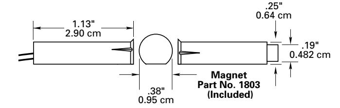
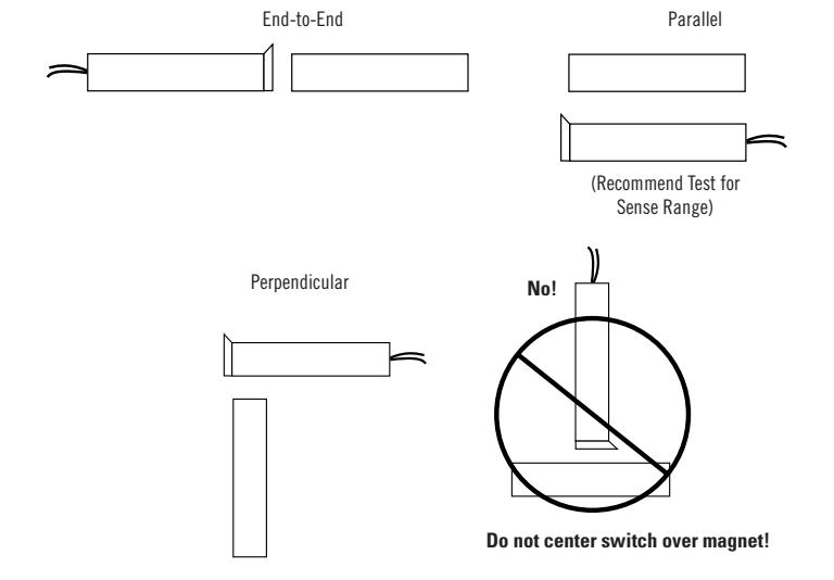
Figure 1
GuardSwitch™ Series 100
Non-Contact Interlock/Position Switch
124 124-1U-03V 124-2U-03V

Installation
- Determine the position of the switch and the actuator magnet so the labels are end-to-end, parallel or perpendicular (see Figure 1). Do not center switch over the actuator.
- 2. Mount the switch on or in the stationary frame of the machine and mount the actuator magnet on or in the moveable guard, door or gate. For mounting in the frame, slightly overdrill 1/4" dia. x 1-5/16" holes. Keep the switch and actuator magnet within the listed sense range: 0.2" (0.5cm).
- 3. Mounting on or in ferrous material will reduce the sense range a minimum of 50%.
- 4. No hardware is provided with the switch or actuator magnet. 1/4" (0.6cm) pushnuts or split-ring clamps are recommended for securing the cylindrical housing.
- 5. Particular care must be taken to determine the actual load of the switch circuit. Surges from coils, motors, contactors, solenoids and tungsten filaments must be considered. Transient protection, such as back-to-back zener diodes (Tranzorb®) or an RC network, is recommended for such loads to ensure that maximum ratings of the switch are not exceeded.
General Specifications
| Enclosure | ABS Plastic | |||
|---|---|---|---|---|
| Temperature Range | -40°F to 180°F (-40°C to 80°C) | |||
| Environmental | Hermetically Sealed Contact Switch | |||
| Sealed in Polyurethane | ||||
| NEMA Rating | 1, 2, 3, 4, 4X, 5, 6, 12 | |||
| Response Time | 1 msec | |||
| Life Cycles | 100,000 | |||
| Lead Type/O.D. | 3' (0.9m) 22 AWG | |||


Ordering/Electrical Specifications
| PART NUMBER |
CONTACT1
CONFIG. |
LOAD RATING
MAXIMUM, AC/DC |
SWITCHING VOLTAGE
MAXIMUM, AC/DC |
SWITCHING CURRENT
MAXIMUM, AC/DC |
CONTACT
RESISTANCE |
SENSE RANGE2
NOMINAL |
BREAK RANGE
NOMINAL |
LEAD LENGTH
NOMINAL |
|---|---|---|---|---|---|---|---|---|
| 124-1U-03V | N.O. | 15VA | 120V @0.11A | 0.5A @30V | 0.2 Ohms | 0.2"(@0.5cm) | 0.8"(@2.0cm) | 3'(0.9m) |
| 124-2U-03V | SPDT | 15VA | 120V @0.11A | 0.5A @30V | 0.2 Ohms | 0.2"(@0.5cm) | 0.8"(@2.0cm) | 3'(0.9m) |
| 124-U | Actuator Only Included with all switches unless otherwise noted. | |||||||
Warning— Each electrical rating is an individual maximum and cannot be exceeded!
- 1 Configuration with actuator away from the switch
- 2 Proximity of ferrous materials usually reduces sense range typically by 50%. The shape and type of material cause a wide diversity of effects. Testing is required to determine actual sense range for specific applications.

www.ge-security.com/industrial
12345 SW Leveton Drive Tualatin, OR 97062 Phone: 800-247-9447 Fax: 503-691-7563