Edwards Signaling 116EXST-EK Installation Instructions
Open the original PDF document
View PDF

Cheshire, CT 06410 203-699-3300 (Ph) 203-699-3365 (Cust. Serv. Fax) 203-699-3078 (Tech. Serv. Fax)
Installation Instructions for 116EX Series AdaptaBeacon® Strobe Lights for Use in Hazardous Locations
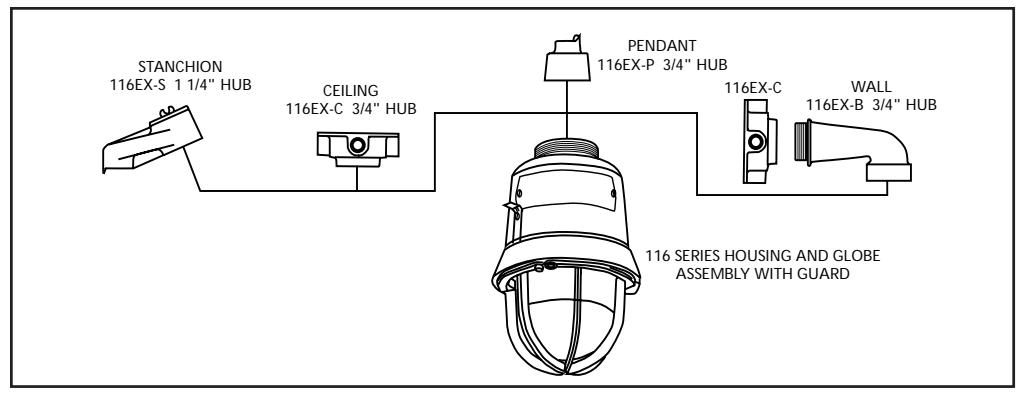
Figure 1. Mounting Options
Description
The 116EX Series AdaptaBeacon strobe signaling appliances are intended for general utility signaling use. The strobes are UL and cUL listed for use in Class I, Division 1, Group C and D, Class I, Division 2, Group A, B, C and D, Class II, Division 1, Group E, F and G, Class II, Division 2, Group F and G, and Class III Division 1 and 2 hazardous locations with operating temperature codes per Table 2.
The strobes are UL and cUL Listed, as Type 3R and 4X enclosures. Additionally, the 120V AC strobes are UL and cUL listed as Marine enclosures.
The strobe flashes a 360-degree beam of light approximately 65 times per minute.
The 12 - 48V DC strobes are available in pendant, bracket, ceiling, or stanchion mount models (Figure 1).
Installation

WARNING
To reduce the risks of ignition of hazardous atmospheres and shock, do not apply power to the unit until installation has been completed and unit is tightly assembled and secured.
Install this unit in accordance with the applicable requirements in the latest edition of the National Electrical Code and Canadian Electrical Code.
-
1. Mount using the following applicable method.
- a. Pendant Mount Models (Figure 2): Install the catalog number 116EX-P, pendant mounting module, to the main housing. Install explosionproof hanger box (not supplied). Secure 3/4" (19 mm) NPT threaded conduit (not supplied) to the box. Install the unit on the conduit. Proceed to step 2.
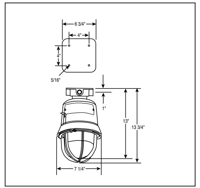
- b. Ceiling Mount Models (Figure 3): Mount the catalog number 116EX-C, ceiling/wall mounting module, using appropriate hardware (not supplied) suitable for the mounting surface. Proceed to step 2.
- c. Bracket Mount Models (Figure 4): Install the catalog number 116EX-C ceiling/wall mounting module using appropriate hardware (not supplied) for the mounting surface. Install the catalog number 116EX-B wall mounting elbow to the wall box. Run the unit's wiring through the elbow to the wall box. Proceed to step 2.
- d. Stanchion Mount Models (Figure 5): Install the catalog number 116EX-S, stanchion mounting module, to the main housing. Run the unit's wires through the 1 1/4" conduit to the appropriate junction box. Install the unit on the conduit. Proceed to step 2.
- 2. Connect field earth ground wire to ground screw or earth ground via conduit system.
- 3. Using wire nuts, connect the incoming (+) or white wire to the unit's two (+) white wires and the incoming (-) or black wire to the unit's two (-) black wires. See Table 2 for required supply wire temperature ratings.
- 4. As appropriate, install the fixture on the mounting module.

WARNING
To reduce the risk of ignition of hazardous atmospheres and shock, keep assembly tightly closed when circuits are energized.
5. Apply power to the unit and ensure proper function.
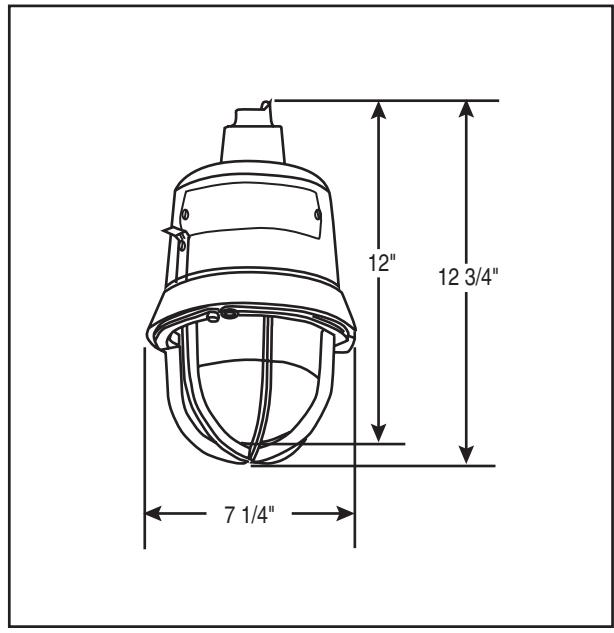
Figure 2. Detail of Pendant Mounting Figure 3. Detail of Ceiling Mounting
Maintenance
Disassemble the unit as follows (Figure 6):

WARNING
To reduce the risk of ignition of hazardous atmospheres and shock, keep assembly tightly closed when circuits are energized.
To reduce the risk of ignition of hazardous atmospheres and shock, disconnect from the supply and circuit and allow five (5) minutes for stored energy to dissipate before disassembling the unit.
- 1. Loosen the (3) guard screws and remove the guard.
- 2. Loosen the globe and ring assembly set screw. Insert a suitable tool into the notches in the globe and ring assembly and loosen the assembly by prying in a
- counterclockwise direction. Remove the ring and globe assembly.
- 3. Refer to Table 1 for the correct replacement catalog number and replace the necessary part.
- 4. To replace, simply screw the unit on until it seats firmly onto its gasket. Tighten the unit another 1/8 to 1/4 turn. Tighten the setscrew.
- 5. Reinstall the guard, where applicable, and secure using the three supplied screws.
- 6. After the unit is assembled, apply power and make sure the unit functions properly.
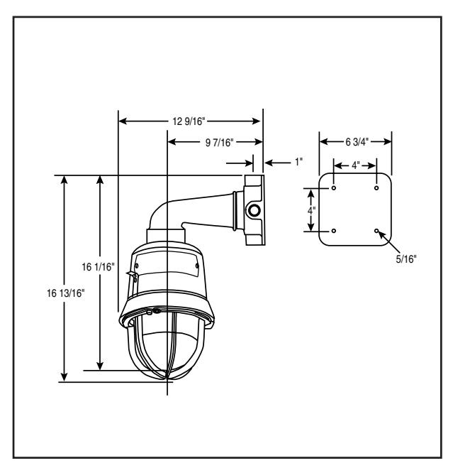
Figure 4. Detail of Wall Bracket Mounting Figure 5. Detail of Stanchion Mounting
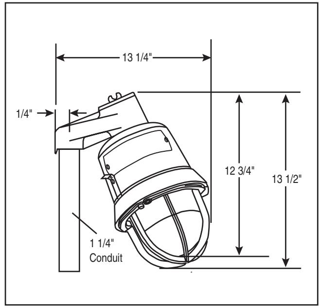
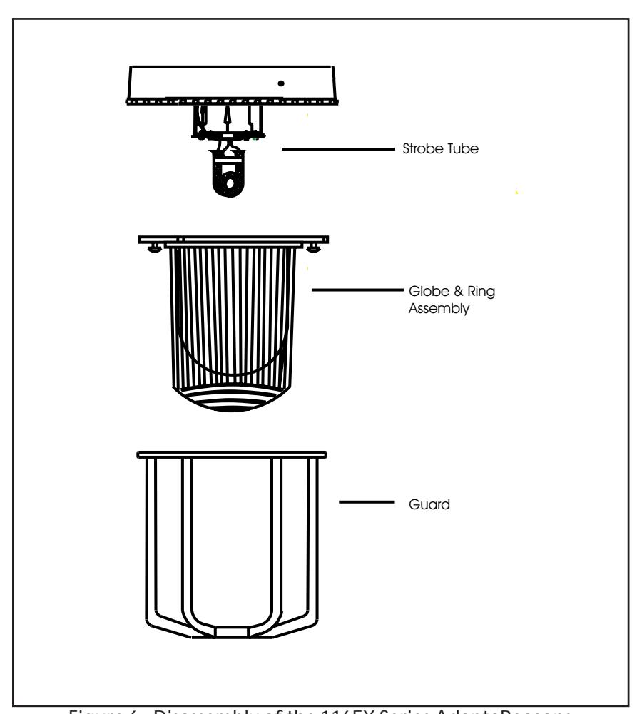
Figure 6. Disassembly of the 116EX Series AdaptaBeacons
Table 1. 116 Series AdaptaBeacons
| Description |
Catalog
Number |
Electrical
Ratings |
Conduit
Size |
Flash
Rate |
Strobe Tube
Replacement |
|---|---|---|---|---|---|
|
Housing Less
Mounting Module |
116EXST*-EK |
12 - 48V DC
1.2 - 0.38A |
N/A |
Approx.
65 fpm |
92-ST |
|
Ceiling/Wall
Mounting Module |
116EX-C | N/A | 3/4" NPT | N/A | N/A |
|
Pendant
Mounting Module |
116EX-P | N/A | 3/4" NPT | N/A | N/A |
|
Stanchion
Mounting Module |
116EX-S | N/A | 1 1/4" NPT | N/A | N/A |
|
Wall Bracket
Mounting Elbow |
116EX-B | N/A | N/A | N/A | N/A |
* Letter in this position denotes color of the globe: A - amber, B - blue, C - clear, G - green, R - red or M - magenta
Table 2. Ratings
| Operating Temperature | |||||||
|---|---|---|---|---|---|---|---|
|
Ambient
Temp. |
Supply Wire
Temp. Marking |
Class I, Div. 2
Groups A, B |
Class I, Div. 1 & 2
Groups C, D |
Class II & III, Div. 1
Groups E, F, G |
Class II & III, Div. 2
Group G |
||
| 40°C | 75°C | T3 (200°C) | T6 (85°C) | T4A (120°C) | T4A (120°C) | ||
| 55°C | 90°C | T3 (200°C) | T6 (85°C) | T4 (135°C) | T4 (135°C) | ||
| 65°C | 105°C | T2D (215°C) | T6 (85°C) | T4 (135°C) | T4 (135°C) | ||
Contacting Edwards:
Phone: (203) 699-3300
E-Mail: techsupport@edwards-signals.com
customerservice@edwards-signals.com
Website: http://www.edwards-signals.com
P/N 3100757 ISSUE 1
P/N 3100757 OFFSET SPEC
ARDOUS LOCATIONS SERIES 116EX ADAPTABEACONS FOR USE IN HAZ-INSTALLATION INSTRUCTIONS FOR CATALOG
WITH PART NUMBER ON THE OUTSIDE. THREE TIMES TO DIMENSIONS SHOWN ON DETAIL (1) 11" X 17" SHEET PRINTED BOTH SIDES. FOLD
MATERIAL: STANDARD WHITE OFFSET STOCK
GROUND CHARACTERS: TO BE BLACK ON WHITE BACK-
REDUCED TO ACTUAL SIZE. NOTE: MECHANICALS HAVE ALREADY BEEN
CHESHIRE, CT 06410 90 FIELDSTONE COURT EDWARDS SIGNALING TECHNICAL WRITING RETURN MECHANICALS TO:
FOLD DETAIL REFERENCE ONLY
ECN: 04-C1703 Issue: 01 File: 3100757 Approved by: KRT