Edwards Signaling 116DEXST-FJ Installation Instructions
Open the original PDF document
View PDF

Cheshire, CT 06410 203-699-3300 (Ph) 203-699-3365 (Cust. Serv. Fax) 203-699-3078 (Tech. Serv. Fax)
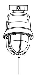
Installation Instructions for 116DEXSTC-FJ AdaptaBeacon® Fire Alarm Strobe Lights for Use in Hazardous Locations
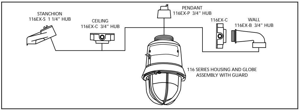
Figure 1. Mounting Options
Description
The 116DEXSTC-FJ AdaptaBeacon is an in-rush current limited strobe light. When pendant, wall or ceiling mounted, it is UL1971 Listed Signaling Appliance for the Hearing Impaired. Stanchion mount models are UL 1638 Listed for Private Mode Emergency Signaling. All models are CSFM Listed.
The strobe is intended for indoor use in UL listed compatiable fire alarm systems and other applications requiring electrical supervision of signaling circuit field wiring. This strobe flashes a 360-degree beam of light approximately 65 times per minute with a UL 1971 60 cd wall and ceiling light output per Figure 7.
When assembled in accordance with these instructions, the 116DEXSTC-FJ visual strobe signal is UL Listed for use in Class I, Division 1, Groups C and D, Class I, Division 2, Groups A, B, C and D, Class II Division 1, Group E, F and G, Class II, Division 2, Group F and G, and Class III Division 1 and 2 hazardous locations with Operating Temperature Codes per the following chart. See Table 1 for Electrical Specifications.
This strobe is UL and cUL Listed as a Type 3R and 4X enclosure. See Figure 1.
Installation
Install this unit in accordance with the applicable requirements in the latest edition of the National Fire Alarm Code (NFPA 72), National Electrical Code (NFPA 70), and Canadian Electrical Code.

WARNING
To reduce the risks of ignition of hazardous atmospheres and shock, do not apply power to the unit until installation has been completed and unit is tightly assembled and secured.
- a. Pendant Mount Models (Figure 2): Install the catalog number 116EX-P, pendant mounting module, to the main housing. Install explosionproof hanger box (not supplied). Secure 3/4" (19 mm) NPT threaded conduit (not supplied) to the box. Install the unit on the conduit. Proceed to step 2.
- b. Ceiling Mount Models (Figure 3): Mount the catalog number 116EX-C, ceiling/wall mounting module, using appropriate hardware (not supplied) suitable for the mounting surface. Proceed to step 2.
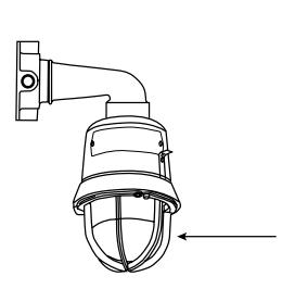
- c. Bracket Mount Models (Figure 4): Install the catalog number 116EX-C ceiling/wall mouting module using appropriate hardware (not supplied) for the mounting surface. Install the catalog number 116EX-B wall mounting elbow to the wall box. Run the unit's wiring through the elbow to the wall box. Proceed to step 2.
- d. Stanchion Mount Models (Figure 5): Install the catalog number 116EX-S, stanchion mounting module, to the main housing. Run the unit's wires through the 1 1/4" conduit to the appropriate junction box. Install the unit on the conduit. Proceed to step 2.
- 2. Connect field earth ground wire to ground screw or earth ground via conduit system.
- 3. Wire the unit in accordance with Figure 6. See Table 3 for required supply wire temperature ratings.
- 4. As appropriate, install the fixture on the mounting module.

WARNING
To reduce the risk of ignition of hazardous atmospheres and shock, keep assembly tightly closed when circuits are energized.
1. Mount using the following applicable method. 5. Apply power to the unit and ensure proper function.
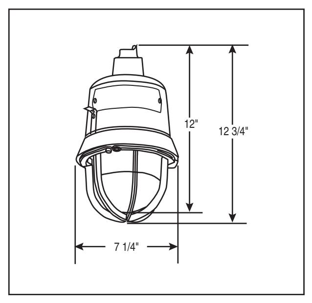
Figure 2. Detail of Pendant Mounting
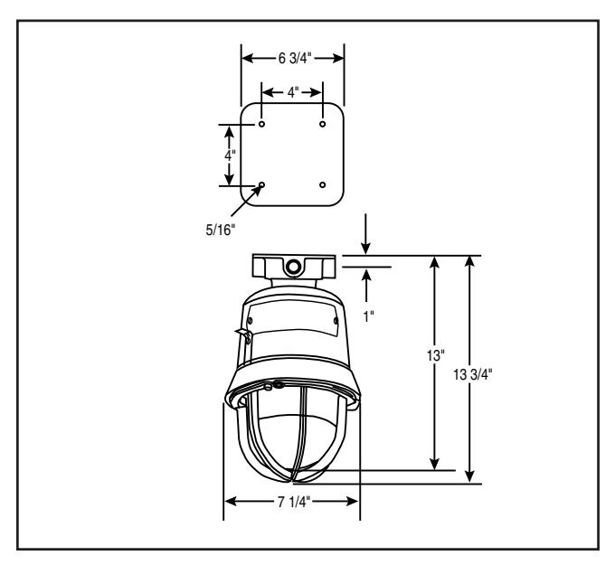
Figure 3. Detail of Ceiling Mounting
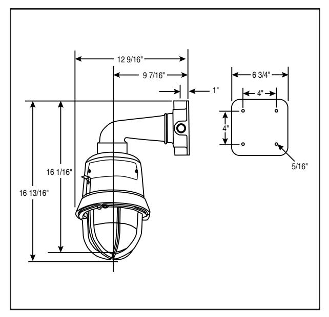
Figure 4. Detail of Wall Bracket Mounting
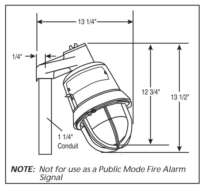
Figure 5. Detail of Stanchion Mounting
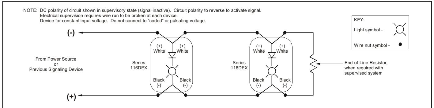
NOTE: For non-fire alarm use , i.e. without field wire supervision , installer can tie the two white leads together and tie the two black leads together.
Figure 6. Wiring Diagram
Maintenance
Disassemble the unit as follows (Figure 8):

WARNING
To reduce the risk of ignition of hazardous atmospheres and shock, keep assembly tightly closed when circuits are energized.
To reduce the risk of ignition of hazardous atmospheres and shock, disconnect from the supply and circuit and allow five (5) minutes for stored energy to dissipate before disassembling the unit.
1. Loosen the (3) guard screws and remove the guard.
- 2. Loosen the globe and ring assembly set screw. Insert a suitable tool into the notches in the globe and ring assembly and loosen the assembly by prying in a counterclockwise direction. Remove the ring and globe assembly.
- 3. Refer to Table 2 for the correct replacement catalog number and replace the necessary part.
- 4. To replace, simply screw the unit on until it seats firmly onto its gasket. Tighten the unit another 1/8 to 1/4 turn. Tighten the setscrew.
- 5. Reinstall the guard, where applicable, and secure using the three supplied screws.
- 6. After the unit is assembled, apply power and make sure the unit functions properly.
Table 1. 116DEXSTC-FJ AdaptaBeacon Strobe Light Electrical Specifications
| Voltage Designation* |
Max RMS Operating
Current (A)** |
|---|---|
| Regulated 24V DC | 0.802 |
| Regulated 24V FWR | 1.140 |
CAUTION: To prevent damage to the signal circuit and to otherwise assure continued proper functioning, DO NOT operate the unit outside of the Regulated 24V DC/FWR voltage range of 16 - 33V DC/V FWR.
Table 2. 116DEXSTC-FJ
| Description |
Catalog
Number |
Electrical
Ratings |
Conduit
Size |
Flash
Rate |
Strobe Tube
Replacement |
|---|---|---|---|---|---|
|
Housing Less
Mounting Module |
116DEXSTC-FJ |
16 - 33V DC
0.802/1.104A |
N/A |
Approx.
65 fpm |
92-ST |
|
Ceiling/Wall
Mounting Module |
116EX-C | N/A | 3/4" NPT | N/A | N/A |
|
Pendant
Mounting Module |
116EX-P | N/A | 3/4" NPT | N/A | N/A |
|
Stanchion
Mounting Module |
116EX-S | N/A | 1 1/4" NPT | N/A | N/A |
|
Wall Bracket
Mounting Elbow |
116EX-W | N/A | N/A | N/A | N/A |
Table 3. Ratings
| Operating Temperature | |||||
|---|---|---|---|---|---|
|
Ambient
Temp. |
Supply Wire
Temp. Marking |
Class I, Div. 2
Groups A, B |
Class I, Div. 1 & 2
Groups C, D |
Class II & III, Div. 1
Groups E, F, G |
Class II & III, Div. 2
Group F, G |
| 40°C | 75°C | T2D (215°C) | T6 (85°C) | T4A (120°C) | T4A (120°C) |
| 55°C | 90°C | T2C (230°C) | T6 (85°C) | T4 (135°C) | T4 (135°C) |
* The designation Regulated 24 refers to the voltage range of 16 - 33 volts.
** The Max RMS Operating Current is defined as the current rating over the entire voltage range.
WALL BRACKET MOUNTING ANGLE (DEGREES) VERTICAL PLANE HORIZONTAL PLANE zero 100% 100% 5 90% 90% 10 90% 90% 15 90% 90% 20 90% 90% 25 90% 90% 30 90% 75% 35 65% 75% 40 46% 75% 45 34% 75% 50 27% 55% 55 22% 45% 60 18% 40% 65 16% 35% 70 15% 35% 75 13% 30% 80 12% 30% 85 12% 25% 90 12% 25% Compound 45 24% UL1971 REQUIRED DISPERSION AS % OF CD RATING
Effective Candela Light Output for Wall Bracket Mount Vertical Plane
(Zero degree angle at side of globe)
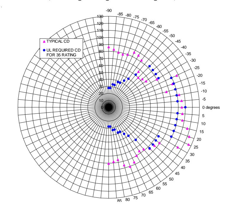
UL 1971 Hearing Impaired: 60 cd wall
|
CEILING
MOUNTING |
UL1971
REQUIRED X & Y PLANE DISPERSION |
|
|---|---|---|
|
ANGLE
(DEGREES) |
AS % OF CD
RATING |
|
| 0 | 100% | |
| 5 | 90% | |
| 10 | 90% | |
| 15 | 90% | |
| 20 | 90% | |
| 25 | 90% | |
| 30 | 75% | |
| 35 | 75% | |
| 40 | 75% | |
| 45 | 75% | |
| 50 | 55% | |
| 55 | 45% | |
| 60 | 40% | |
| 65 | 35% | |
| 70 | 35% | |
| 75 | 30% | |
| 80 | 30% | |
| 85 | 25% | |
| 90 | 25% | |
| Compound 45 | 24% | |
Effective Candela Light Output for Ceiling Mount X & Y Planes (Zero degree angle at bottom of of globe)
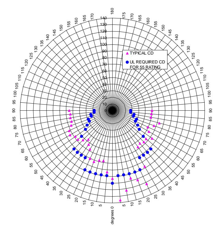
UL 1971 Hearing Impaired: 60 cd ceiling
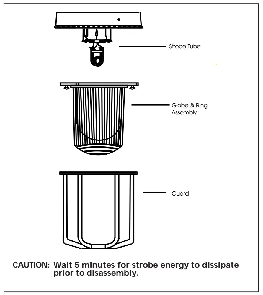
Figure 8. Disassembly of the 116DEXSTC-FJ AdaptaBeacon
Contacting Edwards:
Phone: (203) 699-3300
E-Mail: techsupport@edwards-signals.com
customerservice@edwards-signals.com
Website: http://www.edwards-signals.com
P/N 3100759 ISSUE 1