Edwards Signaling 114ST Series Installation Instructions
Open the original PDF document
View PDF

Installation Instructions for 114 Series Strobe
Description
The 114 Series Strobe is a UL and cUL listed signaling appliance in a NEMA 4X and IP65 rated enclosure. Separate models are available for surface and pipe mounting.
Specifications
|
Catalog
Number |
Voltage | Current | Mounting |
Replacement
Strobe |
|---|---|---|---|---|
| 114SST*-EK | 12-48V DC | 0.350A | Surface | 114-ST |
| 114PST*-EK | 12-48V DC | 0.350A | 1/2" Pipe | 114-ST |
*Letter in this position indicates lens color: A - amber, B - blue, C - clear, G - green, or R - red
Installation

WARNINGS
To prevent electrical shock, ensure that power is turned off before installing the signal or performing any maintenance.
Conduit Mounting (Figure 1)
- Thread the 12" (45.7 cm) signal wire leads through 1/2" (13mm) conduit into an approved conduit outlet box.
- 2. Thread the conduit onto the base of the signal.
- 3. Using wire nuts (not supplied), connect the signal's wire leads as shown in Figure 1. Polarity must be observed.
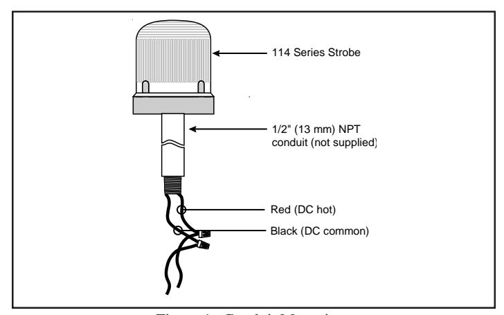
Figure 1. Conduit Mounting
Panel Mounting (Figure 2)
Note: The integrity of the outdoor, NEMA 4X, and IP65 rating on the panel assembly at the interface with the 114 Series Visual Indicator relies on the construction and configuration details of the mounting surface. Installer should evaluate.
- 1. Place the mounting gasket (supplied) over the hole in the panel and route the signal wires through the gasket and the hole in the panel.
- 2. Insert the base through the hole in the panel and screw the locking nut (supplied), with the raised locking edge facing the mounting surface, onto the base to secure the beacon.
- Using wire nuts (not supplied), connect the signal's wire leads as shown in Figure 2. Polarity must be observed.
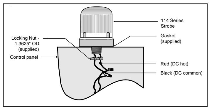
Figure 2. Panel Mounting
Maintenance

WARNINGS
To prevent electrical shock, ensure that power is turned off before installing the signal or performing any maintenance.
To avoid risk of injury, install lens before energizing.
Cleaning
The module lens exterior surfaces should be periodically cleaned with a soft clean cloth using water and a mild detergent to maintain optimum light visibility. Disconnect power before cleaning.
Light Source Replacement
-
Conduit Mounted Modules: Disconnect wiring and, if necessary, unscrew base from conduit (Figure 1).
- Panel Mounted Modules: Disconnect wiring and remove locking nut securing the base to the panel (Figure 2).
- Remove screws securing the lens to the base from bottom of base and remove lens.
- 3. Unplug strobe tube and plug in new strobe tube, Cat. No. 114-ST. Replace lens on base and secure with screws removed in step 2.
Table 1. Programming Logic Controller (PLC) Compatibility: PLC output to meet following product input parameters.
| Cat. No. |
Operating voltage
(Volts) |
Max. off state
leakage current (mA) |
Continuous on current (mA) |
Surge (inrush/duration)
(Amps/milliSeconds) |
|---|---|---|---|---|
| 114SST*-EK | 24V DC | 7 | 350 | 0.45A / 0.02 ms |
| 114PST*-EK | 24V DC | 7 | 350 | 0.45A / 0.02 ms |