Edwards Signaling 110 Series Installation Instructions
Open the original PDF document
View PDF

Installation Instructions for Screw Base Beacons
Description
The Edwards 110 Series are CE Marked Screw Base Beacons that can be installed in a conventional light socket. They are available in either strobe or flashing incandescent and in five different lens colors. See Table 1 for additional specifications.
No disassembly or wiring required for installation.
Specifications
| 110ST*-N5 | Strobe | 120V AC 50/60 Hz |
|---|---|---|
| 110FIN*-N5 | Flashing Incandescent | 120V AC 50/60 Hz |
*Signifies lens color: A - amber, B - blue, C - clear, G - green, or R - red
Installation
Screw beacon into a conventional light socket and apply power.
Maintenance
Lamp Replacement for Incandescent Units
1. Disconnect power.
- 2. Remove two screws from lens and remove lens as shown in Figure 1.
- 3. Press down on bulb and turn counterclockwise to remove.
- 4. Insert replacement bulb (Table 1) into lamp socket (Figure 1), push down and turn clockwise until it locks into place.
- 5. Ensure o-ring seal is in place and replace lens and secure using two screws removed in step 2.
Strobe Tube Replacement for Strobe Units
- Disconnect power.
- 2. Remove two screws from lens and remove lens as shown in Figure 2.
- 3. Remove two screws securing the PC board to the base and remove the PC board.
- 4. Disconnect the power wires from the terminal block on the back of the PC board.
- Connect the power wires to the terminal block on the back of the new PC board. Insert the PC board into the base and secure using the two screws removed in step 3.
- 6. Ensure o-ring seal is in place and replace the lens and secure using two screws removed in step 2.
| Catalog Number | Description |
|---|---|
| 110-LR | Replacement Lens, Red |
| 110-LA | Replacement Lens, Amber |
| 110-LB | Replacement Lens, Blue |
| 110-LG | Replacement Lens, Green |
| 110-LC | Replacement Lens, Clear |
| 110LS-ST-N5 | Replacement Strobe Tube PC Board |
| Industry Std. 15T7DC | Replacement Incandescent Lamp |
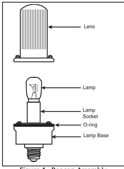
Figure 1. Beacon Assembly
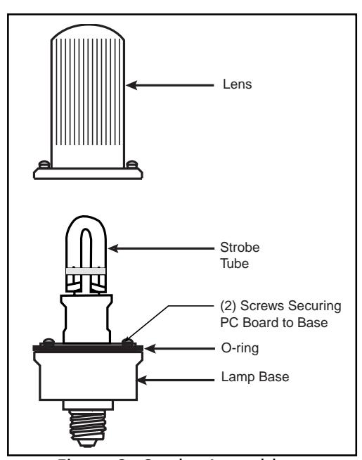
Figure 2. Strobe Assembly