Edwards Signaling 109 Series Installation Instructions
Open the original PDF document
View PDF

Installation Instructions for 109 Series LED Star-Burst™ Visual Indicator
Description
The 109 Series Visual Indicator is a UL and cUL listed signaling appliance in a NEMA 4X and IP65 rated enclosure. The modules can be panel mounted or conduit mounted.
The visual indicator is normally steady-on and with a contact closure, the light will flash. The unit is set for the Rapid Star-Burst flicker flash but with a simple jumper change, can output a 65 flash per minute signal.
The visual indicators are available in red, blue, green, amber or white.
Specifications
|
Catalog
Number |
Voltage | Current |
LED
Color |
|---|---|---|---|
| 109A-G1 | 24V DC | 0.475 A | Amber |
| 109B-G1 | 24V DC | 0.475 A | Blue |
| 109G-G1 | 24V DC | 0.475 A | Green |
| 109R-G1 | 24V DC | 0.475 A | Red |
| 109W-G1 | 24V DC | 0.475 A | White |
| 109A-N5 | 120V 50/60 Hz | 0.140 A | Amber |
| 109B-N5 | 120V 50/60 Hz | 0.140 A | Blue |
| 109G-N5 | 120V 50/60 Hz | 0.140 A | Green |
| 109R-N5 | 120V 50/60 Hz | 0.140 A | Red |
| 109W-N5 | 120V 50/60 Hz | 0.140 A | White |
Installation

WARNING
To prevent electrical shock, ensure that power is turned off before installing the signal.
Conduit Mounting (Figure 1)
- 1. Thread the 18" (45.7 cm) signal wire leads through either 1/2" (13mm) or 3/4" (19 mm) conduit into an approved conduit outlet box. (Product is supplied with a double threaded 1/2" (13mm) internal and 3/4" (19mm) external conduit hub.)
- 2. Using wire nuts (not supplied), connect the signal's wire leads as shown in Figure 1. Polarity must be observed on DC models.

WARNING
To avoid risk of injury, install lens before energizing the unit.
To avoid the risk of injury, do not remove or insert light source when unit is energized.
- 3. Thread the conduit onto the base of the signal.
- 4. Turn on power and verify that the signal operates properly.
Panel Mounting (Figure 2)
Note: The integrity of the outdoor, NEMA 4X, and IP65 rating on the panel assembly at the interface with the 109 Series Visual Indicator relies on the construction and configuration details of the mounting surface. Installer should evaluate.
- 1. Place the mounting gasket (supplied) over the hole in the panel and route the signal wires through the gasket and the hole in the panel.
- 2. Insert the base through the hole in the panel and screw the locking nut (supplied), with the raised locking edge facing the mounting surface, onto the base to secure the beacon.
-
3. Using wire nuts (not supplied), connect the signal's wire leads as shown in Figure 1 or 2. Polarity must be observed on DC models.
- Connect the Red (DC models) or Black (AC models) wire to hot.
- b. Connect the Black (DC models) or White (AC models) to common.
- c. For steady-on applications, trim the yellow wire short and cap using a wire nut (not supplied). For either Star-Burst flicker flash or standard 65 fpm flash, connect the yellow wire to hot to activate.
NOTE: On AC models only, the yellow can be connected to hot, negative or ground to activate the Star-Burst flicker flash or standard 65 fpm flash)
4. Turn on power and verify that the signal operates properly.
Jumper Installation
The 109 Series Visual Indicator is supplied with a default setting of Star-Burst flicker flash. If a standard flash rate of 65 fpm is desired, open the unit by removing (4) screws securing the lens to the base and install jumper on pins 1-2 as shown in Figure 3.
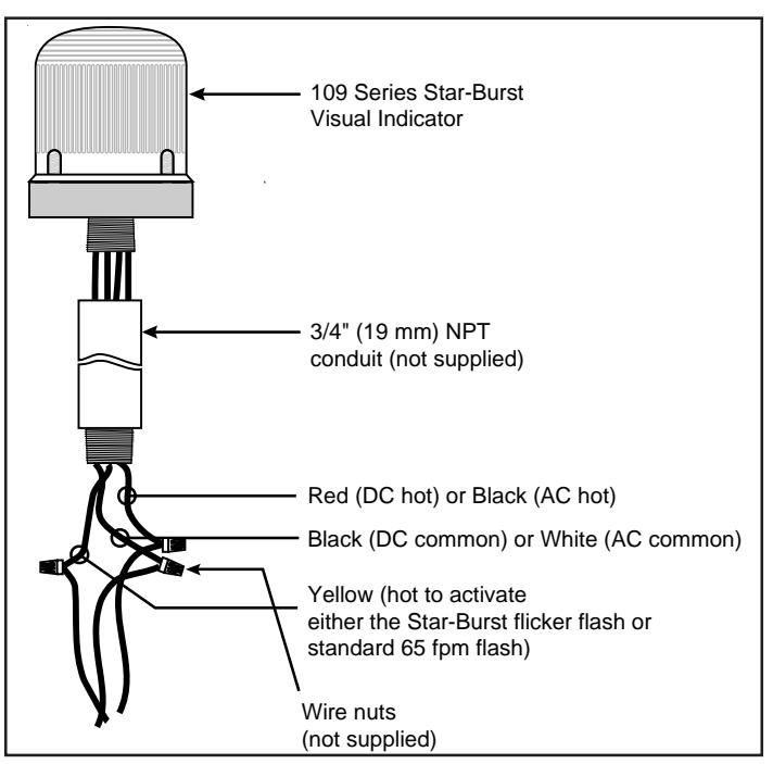
Figure 1. Conduit Mounting (3/4" Shown)
Maintenance

WARNINGS
To avoid risk of injury, install lens before energizing the unit.
To avoid the risk of injury, do not start any maintenance when unit is energized.
Cleaning
The module lens exterior surfaces should be periodically cleaned with a soft clean cloth using water and a mild detergent to maintain optimum light visibility. Disconnect power before cleaning.
Light Source Replacement
-
Conduit Mounted Modules: Disconnect wiring and, if necessary, unscrew base from conduit (Figure 1).
- Panel Mounted Modules: Disconnect wiring and remove locking nut securing the base to the panel (Figure 2).
- 2. Remove (4) screws securing the lens to the base from bottom of base (Figure 4) and remove lens.
- 3. Unplug LED light source and plug in new light source.
NOTE: If the color of the LEDs is changed, the lens color should also be changed to match.
4. Replace lens on base and secure with (4) screws removed in step 2.
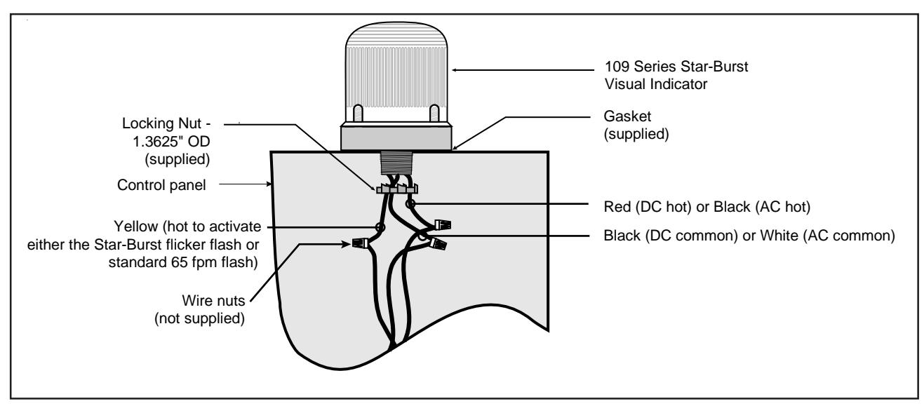
Figure 2. Panel Mounting
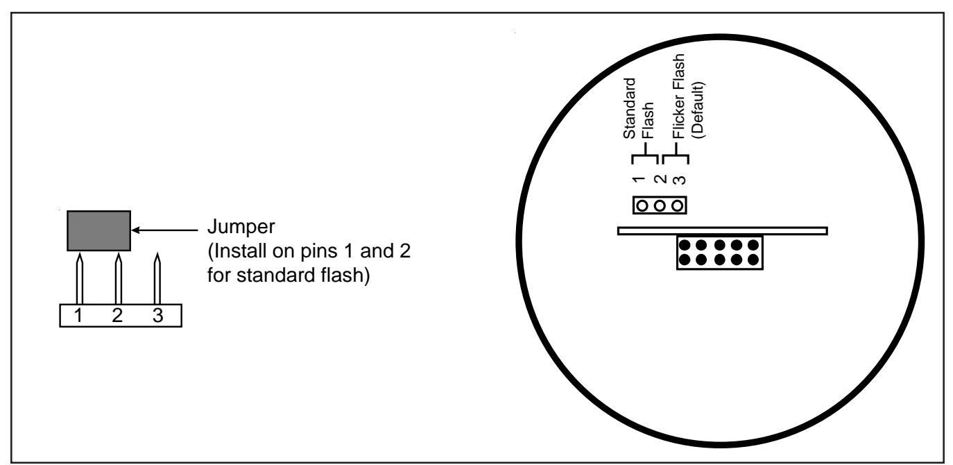
Figure 3. Installing the Jumper (View of inside bottom of unit)
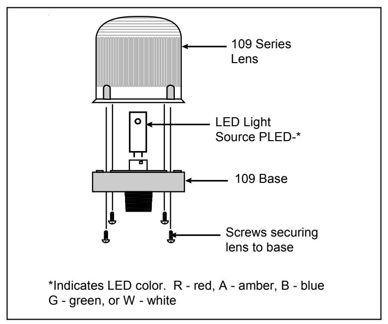
Figure 4. Replacing the Light Source
Table 1. Replacement Parts
|
Catalog
Number |
Lens
Color |
Replacement
Lens |
Replacement
Light Source |
|---|---|---|---|
| 109A-G1 | Amber | 104-LA | PLED-A |
| 109G-G1 | Green | 104-LG | PLED-G |
| 109R-G1 | Red | 104-LR | PLED-R |
| 109B-G1 | Blue | 104-LB | PLED-B |
| 109W-G1 | Clear | 104-LC | PLED-W |
| 109A-N5 | Amber | 104-LA | PLED-A |
| 109G-N5 | Green | 104-LG | PLED-G |
| 109R-N5 | Red | 104-LR | PLED-R |
| 109B-N5 | Blue | 104-LB | PLED-B |
| 109W-N5 | Clear | 104-LC | PLED-W |