Edwards Signaling 105XBRi Chameleon Instructions
Open the original PDF document
View PDF

Installation Instructions for Rebel ChameleonTM 105XBRi Series LED Multi-Status Indicator in NEMA 4X Enclosures
Description
The 105XBRi Series Chameleon Multi-Status LED Indicator is a UL and cUL listed, multi-color LED signaling appliance which, when assembled in accordance with these installation instructions, constitute a UL Listed Type 4X enclosure and are UL Listed for Marine Use. They are designed for use in industrial applications or in applications where a Type 4X enclosure is required. When assembled in accordance with these instructions, the 105XBRi series visual signals are UL Listed for use in Division 2 Hazardous Locations as described in Table 1.
The lights are available in 24V DC and 120V 50/60 Hz. They are available in either Red/Blue/Amber or Red/Green/Amber.
Edwards Signaling's NEW 105XBRi Multi-status Indicator is more "chameleon-like" than ever. With our new adaptive design - one device does it all. With a quick change to the new 105 Chameleon's dip switch settings, these flexible multi-status indicators instantly adapt for use with or without control from an external PLC, PAC, or control relay. Now, regardless of the application you will have just the right device for the job with only half the inventory.
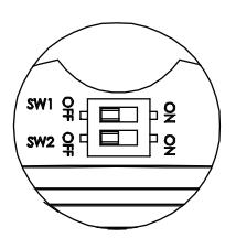
XTRA-SAFE Enabled
The Chameleon 105XBRi devices ship as standard with Edwards Signaling's XTRA-SAFETM Technology (patent pending) Enabled. XTRA-SAFE multi-status indicating devices employ patented combinations of color AND flashrate to provide more definite status indication to those who are color-blind. With XTRA-SAFE, when Chameleon multistatus indicators are turned red, they pulse at a rate of 240 flashes per minute, further emphasizing the urgency which the color red typically connotes. When amber, these devices pulse at a "less urgent" rate of 120 flashes per minute. When Chameleon multi-status indicators are turned blue or green and no other colors are energized, the Chameleon devices remain "steady-on" and do not flash. Even in extreme cases where no color is perceived, flash-rate variation provides a redundant layer of visual indication.
When XTRA-SAFE Technology is enabled, and multiple colors are energized, the device will cycle through the energized colors at the following pre-set flash-rates:
Red: 240 FPM Amber: 120 FPM Green or Blue: 65 FPM
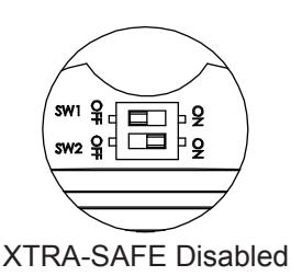
XTRA-SAFE Disabled
While in most cases, the added layer of safety gained by operating a multi-status indicator with XTRA-SAFE Technology is desirable, some applications may not require differentiation in flash rates. In other applications, changes do not correspond to escalating levels of urgency. The adaptive design of the new Chameleon 105 XBRi allows the product to be adapted to accommodate these requirements by configuring the dipswitches as shown in Figure 1 (Applications WITH-OUT a separate PLC or Controller - XTRA-SAFE Technology Disabled). With XTRA-SAFE Disabled, when red or amber, the unit pulses at a rate of 65 flashes per minute. When Chameleon multi-status indicators are turned green or blue and no other colors are energized, the Chameleon devices remain "steady on" and do not flash.
When XTRA-SAFE Technology is disabled, and multiple colors are energized, the device will cycle through the energized colors at 65 FPM.
Externally Controlled
The Chameleon multi-status indicators can also be used in applications where they will be controlled "externally" using a Programmable Logic Controller (PLC) or other such external controller. When externally controlled by a PLC, activation of colors and flash-rate are fully customizable, and can be programmatically determined. In applications, where multiple colors are activated simultaneously, the lights operate on a priority with red highest, amber second and blue or green, the lowest. Refer to Figure 1 (Applications WITH a separate PLC or Controller).Wire color corresponds with each indicated color.
Red wire = Red LED's Yellow wire = Amber LED's Blue with Green tracer wire = Green or Blue LED's
Table 1. Hazardous Location Ratings
| Cat. No. | Class | Division | Group | Operating Temperature |
|---|---|---|---|---|
|
105XBRiRGA24D
105XBRiRGA120A |
I | 2 | A, B, C, D | T5 (100C, 212F) |
| II | 2 | F, G | T5 (100C, 212F) | |
| III | T5 (100C, 212F) | |||
|
105XBRiRBA24D
105XBRiRBA120A |
I | 2 | A, B, C, D | T6 (85C, 185F) |
| II | 2 | F, G | T6 (85C, 185F) | |
| III | T6 (85C, 185F) |
P/N 3101612 ISSUE 3 © 2010
Electrical Specifications

WARNING
To prevent electrical shock, ensure that power is turned off before installing the signal.
| Catalog Number | Electrical Specs | |||
|---|---|---|---|---|
| Red, Green, Amber | ||||
| 105XBRiRGA24D | 24V DC, 0.150 A | |||
| 105XBRiRGA120A | 120V AC*, 0.100 A | |||
| Red, Blue, Amber | ||||
| 105XBRiRBA24D | 24V DC, 0.150 A | |||
| 105XBRiRBA120A | 120V AC*, 0.100 A | |||
* 120 V AC 50/60 Hz
Installation
Installation must be in accordance with local codes. The lens should be positioned up for outdoor applications.

WARNING
To avoid risk of injury, install lens before energizing the unit and do not remove or insert light source when unit is energized.

WARNING - EXPLOSION HAZARD
Do not disconnect equipment unless power has been removed or the area is known to be non-hazardous.

WARNING
To prevent electrical shock, do not connect power until instructed to do so.
1. Select a mounting configuration (Figure 3).
NOTE: When mounting using the Cat. No. 105BM mounting bracket, the Cat. No. 105BX outlet box attachment must also be used as shown in Figure 1.
2. Pull field wiring from conduit into the mounting attachment.

WARNINGS
The 105BX junction box, 105BM mounting bracket and 105PM pipe mount attachments are non-conductive plastic fixtures and do not provide earth-ground continuity when attached to metallic wiring systems. Therefore , they are intended for use with the 105XBRi series visual signals only when earth-grounding is not required.
The 105BX junction box, 105MB mounting bracket and 105PM pipe mount attachments can be used with metallic wiring systems only when installed at the end of the run.
-
3. Install the mounting attachment as follows:
- a. Cat. No. 105BX: Secure the outlet box attachment to the mounting surface using two screws (not supplied) suitable for the surface. Attach the adhesive backed gasket to the top of the 105BX mounting box, being careful to line up the holes in the gasket with the mounting holes in the outlet box.
- b. Cat. No. 105BM: Using the four supplied screws, secure the mounting bracket to Cat. No. 105BX outlet box attachment as shown in Figure 1. Attach the adhesive backed gasket to the top of the 105BM mounting bracket, being careful to line up the holes in the gasket with the mounting holes in the outlet box. Refer to Figure 1.
- c. Cat. No. 105PM: Install 3/4" (19 mm) conduit. Screw the pipe mount attachment onto the 3/4" (19 mm) conduit. Attach the adhesive backed gasket to the top of the 105PM pipe mount attachment, being careful to line up the holes in the gasket with the mounting holes in the outlet box as shown in Figure 2.
- 4. Mount 105XBRi Series as follows. Unscrew the gasketed base from the lens assembly as shown in Figures 1 and 2 and remove the clear gasket from around the base.
- 5. Secure the base to the appropriate mounting attachment using four screws (supplied). Replace the clear gasket on the base with the flared, open end facing down.
Table 2. PLC Compatibility
| Catalog Number |
Operating
Voltage |
Max. off state leak
age current |
Continuous on
current |
Surge (inrush/duration) |
|---|---|---|---|---|
| 105XBRiRGA24D | 24V DC | 5 mA | 150 mA | 28.5 A / 65 μSeconds |
| 105XBRiRBA24D | ||||
| 105XBRiRGA120A | 120V AC 50/60 Hz | 5 mA | 100 mA | 28.5 A / 212 μSeconds |
| 105XBRiRBA120A |
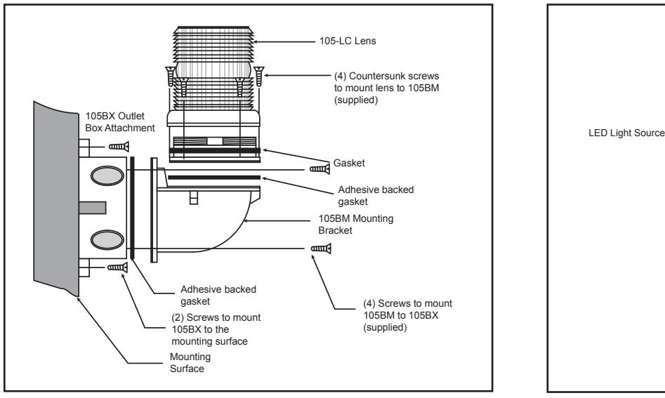
Figure 1. Mounting Cat. No. 105BM Mounting Bracket
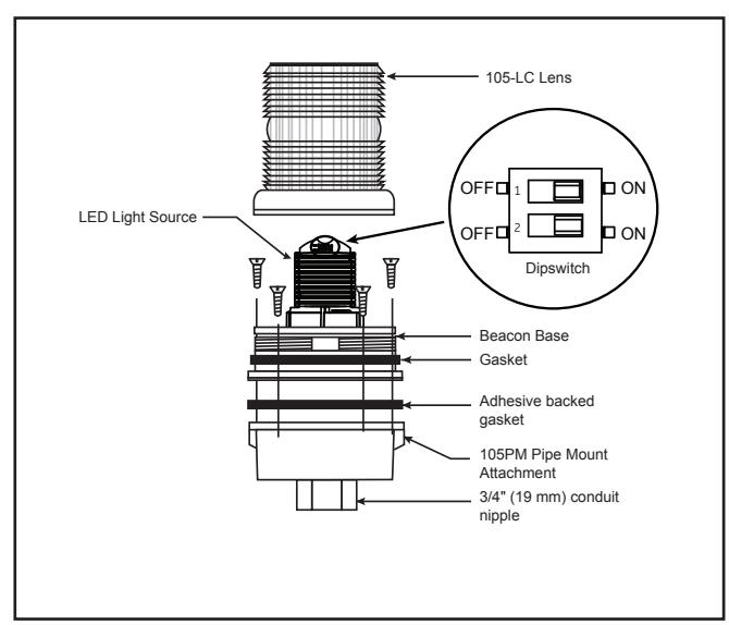
Figure 2. Securing the Beacon to the Mounting Attachment (Pipe Mount Attachment shown)
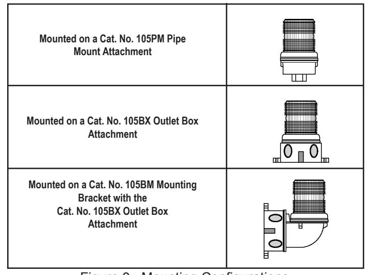
Figure 3. Mounting Configurations
Table 3. Replacement Parts
| Catalog Number | Replacement Lens | Replacement Lamp | ||
|---|---|---|---|---|
| 105XBRiRBA24D | 105-LC | The 148,000 hour** lamp is | ||
| 105XBRiRGA24D | permanently installed. | |||
| 105XBRiRBA120A | The 148,000 hour** lamp is | |||
| 105XBRiRGA120A | 105-LC | permanently installed. | ||
* Median LED Life (L70) based on manufacturer's projections. Refer to http://www.philipslumileds.com/pdfs/WP15.pdf.
-
6. Wire the beacon as follows (Figure 5).
- a. For AC models: There are four 24" wire leads: white (AC neutral), red (for activation of red LEDs), blue with green tracer (for activation of green or blue LEDs-depending on the model) and amber (for activation of amber LEDs). Using wire nuts, connect white lead to AC neutral and connect each of the other three leads to AC hot (120V AC) source.
- b. For DC models: There are four 24" wire leads: black (DC -), red (for activation of red LEDs), blue with green tracer (for activation of green or blue LEDs-depending on the model), and amber (for activation of amber LEDs). Using wire nuts, connect black lead to DC and connect each of the other three leads to DC + (24V DC) source.
- 7. The 105XBRi Multi-Status indicator is shipped with XTRA-SAFE™ Technology Enabled. The unit offers two other field selectable options: (1) for applications without a separate PLC or controller with the XTRA-SAFE™ Technology disabled or (2) for applications with a separate PLC or controller. For more information on the features, refer to the description. For settings, refer to Figure 4.
XTRA-SAFE Enabled
a. Unscrew the lens from the bottom of base (Figures 1 and 2) and remove lens.
-
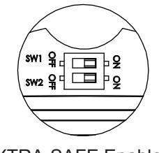
b. Set dipswitches for desired options (Figure 4)
- Applications without a separate PLC or Controller - XTRA-SAFE Technology Disabled: Set dipswitch SW1 to the OFF position and SW2 to the ON position.
Applications with a separate PLC or Controller - Set dipswitches SW1 and SW2 to the OFF position.
With a PLC or other External Controller
- 8. Ensuring that the light source is in place, screw the lens back on the base.
- 9. Apply power and verify operability.
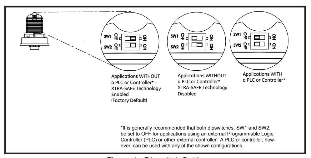
Figure 4. Dipswitch Settings
Maintenance Cleaning

WARNING
To avoid risk of injury, install lens before energizing the unit.

WARNING
To prevent electrical shock, disconnect power before removing the lens.
The module lens exterior surfaces should be periodically cleaned with a soft clean cloth using water and a mild detergent to maintain optimum light visibility. Disconnect power before cleaning.
Lens Replacement
- 1. Unscrew the lens from the bottom of base (Figures 1 and 2) and remove lens.
- 2. Ensuring that the light source is in place, screw the lens back on the base.
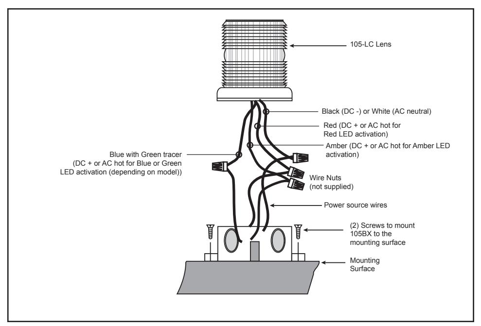
Figure 5. Wiring the 105XBRI Chameleon Series