Edwards Signaling 104 Series Installation Instructions
Open the original PDF document
View PDF

Installation Instructions for 104 Series AdaptaBeacon® Modules in NEMA 4X Enclosures
Cheshire, CT 06410 203-699-3300 (Ph) 203-699-3365 (Cust. Serv. Fax) 203-699-3078 (Tech. Serv. Fax)
Description
The 104 Series AdaptaBeacon is a UL and cUL listed signaling appliance in a NEMA 4X and IP65 rated enclosure. CE Marked. The modules can be panel mounted or conduit mounted.
AdaptaBeacon modules are available in Flashing LED (104FLED), Steady-On LED (104SLED), Flashing Halogen (104FINH), Steady-On Halogen (104SINH) or Flashing Strobe (104ST). The maximum capacitor operating temperature (Tc) is 185°F (85°C).
The modules are available in a variety of colors as listed in Table 1.
|
Catalog
Number |
Voltage | Current |
Illumination
Source |
|---|---|---|---|
| 104FLED(*)-G1 | 24V DC | 0.062 A | 28 LED Cluster |
| 104FLED(*)-N5 | 120V 50/60 Hz | 0.022 A | 28 LED Cluster |
| 104SLED(*)-G1 | 24V DC | 0.062 A | 28 LED Cluster |
| 104SLED(*)-N5 | 120V 50/60 Hz | 0.022 A | 28 LED Cluster |
| 104FINH(*)-G1 | 24V DC | 0.77 A | 9W Halogen Bulb |
| 104FINH(*)-G5 | 24V 50/60 Hz | 0.77 A | 9W Halogen Bulb |
| 104FINH(*)-N5 | 120V 50/60 Hz | 0.25 A | 12W Halogen Bulb |
| 104SINH(*)-G1 | 24V DC | 0.77 A | 9W Halogen Bulb |
| 104SINH(*)-G5 | 24V 50/60 Hz | 0.77 A | 9W Halogen Bulb |
| 104SINH(*)-N5 | 120V 50/60 Hz | 0.25 A | 12W Halogen Bulb |
| 104ST(*)-N5 | 120V 50/60 Hz | 0.12 A | Xenon Strobe Tube |
* Letter in this position signifies color of the lens. For available colors, see Table 1.
Specifications

WARNING
To prevent electrical shock, ensure that power is turned off before installing the signal.
Installation
Conduit Mounting (Figure 1)
- 1. Thread the 18" (45.7 cm) signal wire leads through either 1/2" (13mm) or 3/4" (19 mm) conduit into an approved conduit outlet box. (Product is supplied with a double threaded 1/2" (13mm) internal and 3/4" (19mm) external conduit hub.)
-
2. Wire the beacon as follows:
- a. For AC models, use wire nuts (not supplied) and connect the signal's black and white wire leads to the power source wires as shown in Figure 1. Polarity is not relevant.
- b. For DC models, connect the signal's red wire to the positive power source wire and connect the signal's black wire to the negative power source wire using wire nuts (not supplied). Polarity must be observed. Refer to Figure 1.

WARNINGS
To avoid risk of injury, install lens before energizing the unit.
To avoid the risk of injury, do not remove or insert lamp when unit is energized.
- 3. Thread the conduit onto the base of the signal.
- 4. Turn on power and verify that the signal operates properly.
Panel Mounting (Figure 2)
Note: The integrity of the outdoor, NEMA 4X, and IP65 rating on the panel assembly at the interface with the 104 Series AdaptaBeacon relies on the construction and configuration details of the mounting surface. Installer should evaluate.
- 1. Place the mounting gasket (supplied) over the hole in the panel and route the signal wires through the gasket and the hole in the panel.
- 2. Insert the base through the hole in the panel and screw the locking nut (supplied), with the raised locking edge facing the mounting surface, onto the base to secure the beacon.
-
3. Wire the beacon as follows:
- a. For AC models, use wire nuts (not supplied) and connect the signal's black and white wire leads to the power source wires as shown in Figure 2. Polarity is not relevant.
- b. For DC models, connect the signal's red wire to the positive power source wire and connect the signal's black wire to the negative power source wire using wire nuts (not supplied). Polarity must be observed. Refer to Figure 2.
- 4. Turn on power and verify that the signal operates properly.
Maintenance
A
WARNINGS
To avoid risk of injury, install lens before energizing the unit.
To avoid the risk of injury, do not start any maintenance when unit is energized.
To prevent electrical shock, disconnect all power and wait five (5) minutes for stored energy in strobe modules to dissipate before starting work on unit.
Cleaning
The module lens exterior surfaces should be periodically cleaned with a soft clean cloth using water and a mild detergent to maintain optimum light visibility. Disconnect power before cleaning.
Lamp Replacement
-
1.
Conduit Mounted Modules:
Disconnect wiring and, if necessary, unscrew base from conduit (Figure 1).
- Panel Mounted Modules: Disconnect wiring and remove locking nut securing the base to the panel (Figure 2).
- 2. Remove (4) screws securing the lens to the base from bottom of base (Figure 3) and remove lens.
-
3. Replace halogen lamp or strobe tube as follows (Figure 3):
- a. Halogen Lamp: Grasping the base of the halogen lamp (Do not touch actual halogen lamp envelope), push the halogen lamp down while turning counterclockwise. Then, pull the lamp directly upward to remove from the socket.
Strobe Tube: Grasping the base of the strobe tube ( Do not touch actual strobe tube glass ), pull directly upward to remove the strobe tube from the socket.
- b. Grasping the base of the new lamp or strobe tube, insert in the socket.
- 4. Replace lens on base and secure with (4) screws removed in step 2.
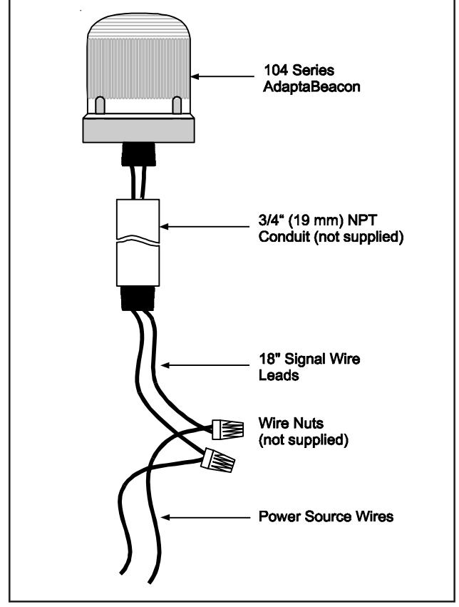
Figure 1. Conduit Mounting (3/4" Shown)
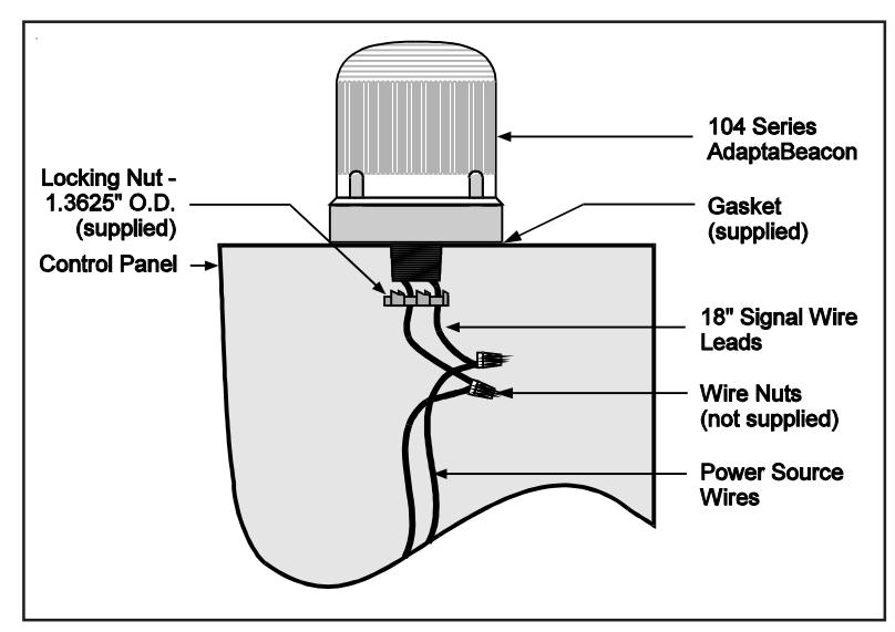
Figure 2. Panel Mounting
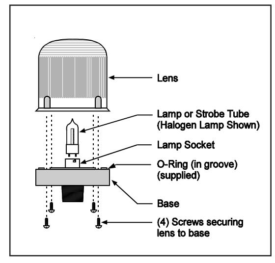
Figure 3. Lamp Replacement
Table 1. Replacement Parts
|
Catalog
Number |
Lens
Color |
Replacement
Lens |
Replacement
Lamp |
|---|---|---|---|
| 104FLEDA-G1 | Amber | 104-LA | * |
| 104FLEDG-G1 | Green | 104-LG | |
| 104FLEDR-G1 | Red | 104-LR | |
| 104FLEDB-G1 | Blue | 104-LB | |
| 104FLEDA-N5 | Amber | 104-LA | * |
| 104FLEDG-N5 | Green | 104-LG | |
| 104FLEDR-N5 | Red | 104-LR | |
| 104FLEDB-N5 | Blue | 104-LB | |
| 104SLEDA-G1 | Amber | 104-LA | * |
| 104SLEDG-G1 | Green | 104-LG | |
| 104SLEDR-G1 | Red | 104-LR | |
| 104SLEDB-G1 | Blue | 104-LB | |
| 104SLEDA-N5 | Amber | 104-LA | * |
| 104SLEDG-N5 | Green | 104-LG | |
| 104SLEDR-N5 | Red | 104-LR | |
| 104SLEDB-N5 | Blue | 104-LB | |
| 104FINHA-G1 | Amber | 104-LA | 50LMP-9WH-D or |
| 104FINHB-G1 | Blue | 104-LB | industry trade no. |
| 104FINHC-G1 | Clear | 104-LC | 1692** (incandescent) |
| 104FINHG-G1 | Green | 104-LG | |
| 104FINHR-G1 | Red | 104-LR | |
| 104FINHA-G5 | Amber | 104-LA | 50LMP-9WH-D or |
| 104FINHB-G5 | Blue | 104-LB | industry trade no. |
| 104FINHC-G5 | Clear | 104-LC | 1692** (incandescent) |
| 104FINHG-G5 | Green | 104-LG | |
| 104FINHR-G5 | Red | 104-LR | |
| 104FINHA-N5 | Amber | 104-LA | 50LMP-12WH-D or |
| 104FINHB-N5 | Blue | 104-LB | industry trade no. |
| 104FINHC-N5 | Clear | 104-LC | 15T7DC** (incandescent) |
| 104FINHG-N5 | Green | 104-LG | |
| 104FINHR-N5 | Red | 104-LR | |
| 104SINHA-G1 | Amber | 104-LA | 50LMP-9WH-D or |
| 104SINHB-G1 | Blue | 104-LB | industry trade no. |
| 104SINHC-G1 | Clear | 104-LC | 1692** (incandescent) |
| 104SINHG-G1 | Green | 104-LG | |
| 104SINHR-G1 | Red | 104-LR | |
| 104SINHA-G5 | Amber | 104-LA | 50LMP-9WH-D or |
| 104SINHB-G5 | Blue | 104-LB | industry trade no. |
| 104SINHC-G5 | Clear | 104-LC | 1692** (incandescent) |
| 104SINHG-G5 | Green | 104-LG | |
| 104SINHR-G5 | Red | 104-LR | |
| 104SINHA-N5 | Amber | 104-LA | 50LMP-12WH-D or |
| 104SINHB-N5 | Blue | 104-LB | industry trade no. |
| 104SINHC-N5 | Clear | 104-LC | 15T7DC** (incandescent) |
| 104SINHG-N5 | Green | 104-LG | |
| 104SINHR-N5 | Red | 104-LR | |
| 104STA-N5 | Amber | 104-LA | 91B-ST |
| 104STB-N5 | Blue | 104-LB | |
| 104STC-N5 | Clear | 104-LC | |
| 104STG-N5 | Green | 104-LG | |
| 104STR-N5 | Red | 104-LR |
* The 100,000 hour LED light source is permanently installed.
** The listed non-halogen lamp may be used in place of the halogen lamp.