Edwards Signaling 103I Series Installation Instructions
Open the original PDF document
View PDF

Installation Instructions for Chameleon<sup>™</sup> 103I Series LED Multi-Status Indicator in NEMA 4X Enclosures

The 103 Series Chameleon Multi-Status LED Indicator is a UL and cUL listed, CE marked multi-color LED signaling appliance in a NEMA 4X and IP65 rated enclosure. The modules can be panel mounted or conduit mounted.
The lights are available in 24V DC and 120V 50/60 Hz. They are available in either red, blue and amber or red, green and amber.
The lights are designed such that any one or all three lights can be activated by either a PLC or contact closure. The first light activated can be either steady or flashing.
Specifications
|
Catalog
Number |
Voltage | Current | Colors |
|---|---|---|---|
| 103I-RGA-N5 | 120V 50/60 Hz | 0.045 A | red, green, amber |
| 103I-RBA-N5 | 120V 50/60 Hz | 0.045 A | red, blue, amber |
| 103I-RGA-G1 | 24V DC | 0.055 A | red, green, amber |
| 103I-RBA-G1 | 24V DC | 0.055 A | red, blue, amber |
Installation
The unit is factory shipped such that a contact closure will cause the first light activated to illuminate steady (unless activated by a PLC). If a second light is activated, the unit will cycle between the two selected colors. Likewise, a third activation will cause the unit to cycle between the three colors: red, amber, green or red, amber, blue.
If it is desired for the first light to illuminate flashing, install the jumper on pins 1 and 2 as shown in Figure 1. A contact closure will then cause the first light activated to illuminate flashing. If a second light is activated, the unit will cycle between the two selected colors. Likewise, a third activation will cause the unit to cycle between three colors: red, amber, green or red, amber, blue.
A
WARNING
To prevent electrical shock, ensure that power is turned off before installing the signal.
Conduit Mounting (Figure 2)
-
If the unit is not being flashed by a PLC and it is desired for the first light to illuminate flashing, the jumper must be installed as follows.
- a. Remove (4) screws securing the lens to the base from bottom of base (Figure 3) and remove lens.
- b. Install the jumper on pins 1 and 2 (Figure 1) for PLC flashing. The unit is supplied with the jumper installed on pins 2 and 3 for a steady illumination.
- c. Replace lens on base and secure with (4) screws removed in step 1a.
- 2. Thread the 18" (45.7 cm) signal wire leads through either 1/2" (13mm) or 3/4" (19 mm) conduit into an approved conduit outlet box. (Product is supplied with a double threaded 1/2" (13mm) internal and 3/4" (19mm) external conduit hub.)

a. For AC models: There are four 18" wire leads: white (neutral), red (for activation of red LEDs), white with green stripe (for activation of green or blue LEDs--depending on model) and amber (for activation of amber LEDs).
Using wire nuts, connect white lead to AC neutral and connect each of the other three leads to AC hot.
b. For DC models: There are four 18" wire leads: black (common), red (for activation of red LEDs), white with green stripe (for activation of green or blue LEDs-depending on model) and amber (for activation of amber LEDs).
Using wire nuts, connect black lead to DC common and connect each of the other three leads to DC hot.
4. Thread the conduit onto the base of the signal.
WARNING To avoid risk of injury, install lens before energizing the unit.
5. Turn on power and verify that the signal operates properly.
Panel Mounting (Figure 3)
Note: The integrity of the outdoor, NEMA 4X, and IP65 rating on the panel assembly at the interface with the 103 Series Chameleon Visual Status Indicator relies on the construction and configuration details of the mounting surface. Installer should evaluate.
-
1. If the unit is not being flashed by a PLC and it is desired for the first light to illuminate flashing, the jumper must be installed as follows.
- a. Remove (4) screws securing the lens to the base from bottom of base (Figure 3) and remove lens.
- b. Install the jumper on pins 1 and 2 (Figure 1) for PLC flashing. The unit is supplied with the jumper installed on pins 2 and 3 for a steady illumination.
- c. Replace lens on base and secure with (4) screws removed in step 1a.
- 2. Place the mounting gasket (supplied) over the hole in the panel and route the signal wires through the gasket and the hole in the panel.
- 3. Insert the base through the hole in the panel and screw the locking nut (supplied), with the raised locking edge facing the mounting surface, onto the base to secure the beacon.
-
4. Wire the beacon as follows:
- a. For AC models: There are four 18" wire leads: white (neutral), red (for activation of red LEDs), white with green stripe or blue (for activation of green or blue LEDsdepending on model) and amber (for activation of amber LEDs).
Using wire nuts, connect white lead to AC neutral and connect each of the other three leads to AC hot.
b. For DC models: There are four 18" wire leads: black (common), red (for activation of red LEDs), white with green stripe or blue (for activation of green or blue LEDs-depending on model) and amber (for activation of amber LEDs).
Using wire nuts, connect black lead to DC common and connect each of the other three leads to DC hot.
5. Turn on power and verify that the signal operates properly.
Maintenance
A
WARNING
To avoid the risk of injury, do not start any maintenance when unit is energized. Reinstall lens beore energizing unit.
Cleaning
A
WARNING
To prevent electrical shock, disconnect power before removing the lens.
The module lens exterior surfaces should be periodically cleaned with a soft clean cloth using water and a mild detergent to maintain optimum light visibility. Disconnect power before cleaning.
Lens Replacement
- 1. Remove (4) screws securing the lens to the base from bottom of base and remove lens.
- 2. Replace lens on base and secure with (4) screws removed in step 1.
Table 1. PLC Compatibility
| Cat. No. |
Operating
voltage Volts |
Max. off state
leakage current mA |
Continuous
on current mA |
Surge
(inrush/duration) A/mSeconds** |
|---|---|---|---|---|
|
103I-RBA-G1
103I-RGA-G1 |
24V DC | 5 | 55 | 0.070/8 |
|
103I-RBA-N5
103I-RGA-N5 |
120V AC | 5 | 45 | 0.100/8 |
* All AC volts at 60 Hz
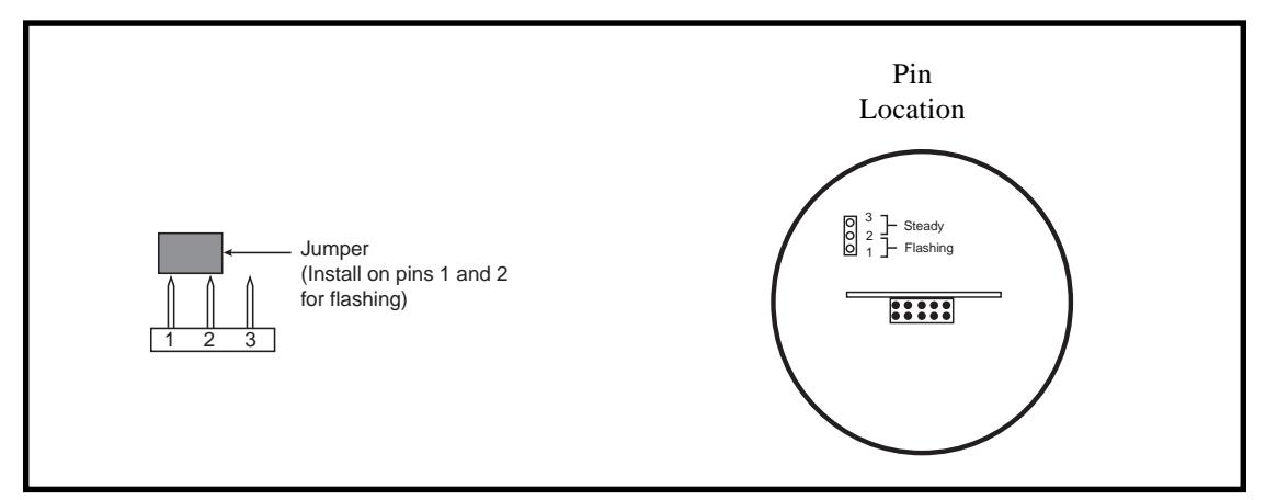
Figure 1. Installing the Jumper
** Amps/milliseconds
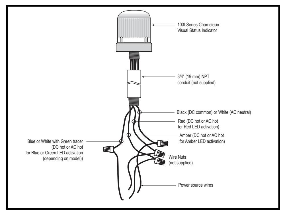
Figure 2. Conduit Mounting (3/4" Shown)
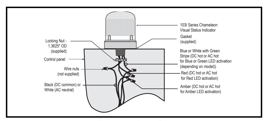
Figure 3. Panel Mounting