Edwards Signaling 102 Series Installation Instructions
Open the original PDF document
View PDF

102 Series TrilipticalTM Stackable Beacon Lighting System Installation Sheet
Description / Operation
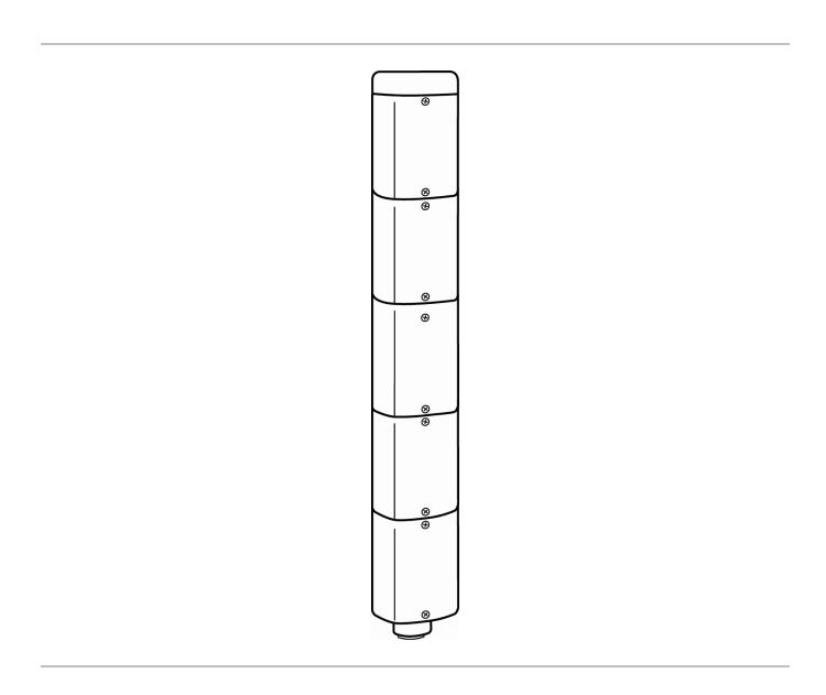
The Edwards Triliptical Stackable Beacon Lighting System is a unique audible-visual signaling device that can contain up to 5 light modules and either a single or multiple tone module in a single "stack."
All components of the Triliptical Stackable Beacon Lighting System are UL and cUL listed subassemblies. The units, when assembled, are UL and cUL listed for indoor and outdoor applications. The enclosures are NEMA 3R, 4X, and IP65 rated.
The optically designed lenses are available in five colors. See "Specifications" on page 3. Each lens module contains a removable cover to allow for easy relamping. The lens module cover features a molded-in gasket for weather tight reliability.
The unit's bases are available in three models. Two models feature shorter bases that are used when a lower profile is desired: one for surface mounting and one for pendant mounting. The other model features a larger base with a terminal block for use with an optional horn assembly. The larger base also functions as a junction box.
A pipe mount kit, Cat. No. 102PMF (sold separately) and one of three extension pipes (sold separately) allows the status indicator to be raised above the mounting surface for increased visibility. It can be used with either the Cat. No. 102TBS or Cat. No. 102PMBS mounting bases.
PLC Compatibility
The electrical input characteristics for PLC compatible signals are listed in Table 3. Signals with these characteristics may be directly connected to PLC output cards that do not exceed these input characteristics.
Installation
Installation must be in accordance with the latest edition of the National Electrical Code and other governing standards and codes for standard installation.
WARNINGS: To prevent electrical shock, do not connect power until instructed to do so.
To prevent abrasion of wiring insulation, ensure that wire passage holes are adequately protected.
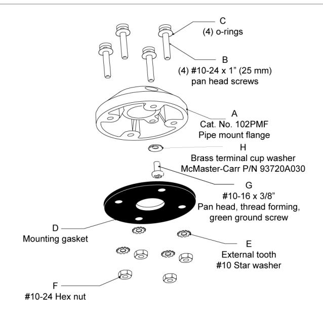
1. If using the 102PMF mounting kit, perform the following:
NOTE: All references below are to Figure 4.
- a. Using the supplied gasket (D) as a guide, mark the four mounting holes and the center clearance hole on an appropriate surface.
- b. Punch the four mounting holes. Punch the wiring clearance hole in the mounting surface to be sufficiently larger than that in the gasket to ensure the wiring insulation is protected from abrasion by the gasket (without interfering with the mounting screw holes), or provide other appropriate wire insulation abrasion protection as needed.
- c. Screw the pipe extension (purchased separately) into the mounting flange.
- d. Ground the flange by pulling the ground wire through the mounting surface clearance hole and center hole of the gasket. Connect earth ground to the bottom of the base mount flange using the ground screw (G) and wire retention terminal cup washer (H).
- e. Pull the remaining field wiring through center clearance hole of mounting surface, center hole of the gasket, pipe mount flange and extension pipe.
- f. Align the mounting gasket (D) and flange (A) on the panel. Secure using (4) #10-24 x 1" (25 mm) pan head screws (B), (4) external tooth #10 star washers (E) and (4) #10-24 hex nuts (F).
- g. Mount the base as instructed below.
- 2. Mount the base using one of the following methods:
NOTE: For indoor applications, the base may be panel mounted or conduit mounted. For NEMA3R, 4X, and outdoor applications, it is recommended that the unit be conduit mounted vertically facing up using either the Cat. No. 102TBS or Cat. No. 102PMBS base.
- a. Cat. No. 102TBS Install base on 3/4" (19 mm) conduit (not supplied). Pull field wiring through conduit entrance hole.
- b. Cat. No. 102PMBS Install base on 3/4" (19 mm) conduit (not supplied). Pull field wiring through conduit entrance hole.
- c. Cat. No. 102DMBS Using the supplied mounting gasket as a template, punch the four mounting holes. Punch the wiring clearance hole in the mounting surface to be sufficiently larger than that in the gasket to ensure the wiring insulation is protected from abrasion by the gasket (without interfering with the mounting screw holes), or provide other appropriate wire insulation abrasion protection as needed. Mount the base to the surface using the (2) screws (supplied).
-
3. Connect field wiring.
- a. Cat. No. 102TBS Connect field wiring to the terminal block as shown in Figure 1.
- b. Cat. No. 102PMBS or Cat. No. 102DMBS Using wire nuts, connect 18" (457 mm) wire leads to field wiring. The six wire leads are marked as follows: Neutral, 1 Bottom, 2, 3, 4 & 5. 1 Bottom denotes the lead for the bottom-most signal in the stack.
- c. If using the optional Cat. No. 102SIGST single tone module or Cat No. 102SIGMT multi-tone module, connect additional field wiring to the terminal block mounted on the signal assembly as shown in Figure 2.
NOTE: The tone module may be wired to sound independently or in conjunction with a light signal.
- (1) To sound tone module independently, connect to separate hot lead.
- (2) To sound tone module with a particular light, connect horn hot terminal to selected light terminal on Cat. 102TBS terminal block.
-
4. Assemble the stackable beacon lighting system (Figure 3).
- a. Pull the captive key in the lens module into the "out" position.
- b. Place the first lens module on top of the base.
- c. Push in the captive key to secure the lens module.
WARNING: To prevent leakage, ensure the magnifier ring on the lens cover and the magnifier ring on the lens module are aligned (Figure 3).
d. Insert the appropriate light source into board grooves at bottom of lens module, ensuring that the four prongs on the PC board are aligned with the plug located in the back of the lens assembly.
NOTE: When using LED light sources, ensure that the color of the LED light source and the lens assembly match.
- e. Place the lens assembly cover on the front of the lens module and secure using two captive screws.
- f. Repeat steps a through e for any remaining modules (up to 5).
- g. Once the last module has been assembled, place the cap on top and secure the cap with the captive screw.
WARNING: To prevent electrical shock, disconnect power to all modules. Wait 5 minutes for stored energy in strobe modules to dissipate before working on unit.
5. Apply power to the unit and verify proper operation.
Maintenance
Light Source Replacement
- 1. Loosen captive screws and remove cover of affected lens module.
- 2. Remove the light source assembly from the lens module.
- 3. Install new light source assembly ensuring that the four prongs on the PC board are aligned with the plug located in the back of the lens module.
WARNING: To prevent leakage, ensure the magnifier ring on the lens cover and the magnifier ring on the lens module are aligned (Figure 3).
4. Replace lens cover and secure using two captive screws.
Cleaning
The lens surfaces should be periodically dusted and cleaned with a dry soft clean cloth to maintain optimum light visibility. If necessary, the outside of the lens may be cleaned with water and a mild detergent on a well rung-out, soft, clean cloth.
Figure 1: Wiring Cat. No. 102TBS
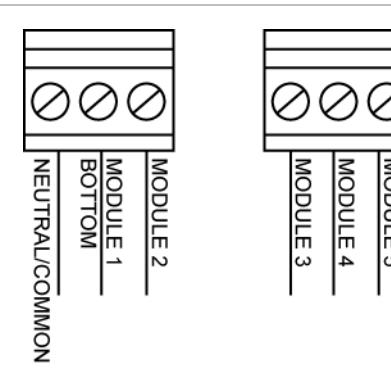
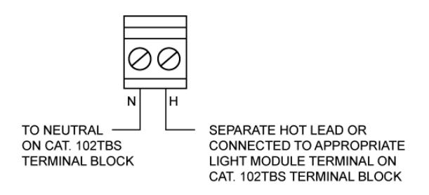
Figure 3: Assembling the stackable status indicator (Cat. No. 102TBS shown for illustration purposes only)
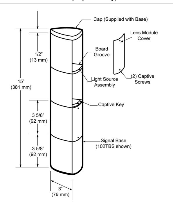
Figure 4: Optional 102PMF Mounting Kit Assembly
Specifications
| Voltage | 24 VDC (-G1) | 120 VAC (-N5) |
|---|---|---|
| Current | ||
| Base Units | ||
| 102TBS | 1.75 A* | 0.60 A* |
| 102DMBS | 1.75 A* | 0.60 A* |
| 102PMBS | 1.75 A* | 0.60 A* |
| Tone Module | ||
| 102SIGMT | 0.05 A | 0.07 A |
| 102SIGST | 0.05 A | 0.07 A |
| Light Modules | ||
| 102LS-SINH | 0.32 A | 0.11 A |
| 102LS-SIN | 0.32 A | 0.08 A |
| 102LS-FINH | 0.32 A | 0.11 A |
| 102LS-FIN | 0.32 A | 0.08 A |
| 102LS-ST | 0.30 A | 0.30 A |
| 102LS-SLED | 0.062 A | 0.022 A |
| 102LS-FLED | 0.062 A | 0.022 A |
| Replacement Lamp | ||
| 102LS-SINH | 50LMP-9WH** | 50LMP-12WH |
| 102LS-SIN | Ind. Trade 303 | 50LMP-10W |
| 102LS-FINH | 50LMP-9WH** | 50LMP-12WH |
| 102LS-FIN | Ind. Trade 303 | 50LMP-10W |
* Currents shown are for a stackable indicator with 5 light modules.
Table 1: Lamp Life (Hours)
| Light Source | Calculated* | Projected** |
|---|---|---|
| 102LS-SINH-G1 | 12,000 | |
| 102LS-SINH-N5 | 20,000 | |
| 102LS-SIN-G1 | 10,000 | |
| 102LS-SIN-N5 | 2,500 | |
| 102LS-FINH-G1 | 12,000 | 15,000 |
| 102LS-FINH-N5 | 20,000 | 25,000 |
| 102LS-FIN-G1 | 10,000 | 12,500 |
| 102LS-FIN-N5 | 2,500 | 3,000 |
| 102LS-ST-G1 | 3,000*** | |
| 102LS-ST-N5 | ||
| 102LS-SLED | 100,000 | |
| 102LS-FLED |
* At nominal operating voltage.
Table 2: Part numbers
| Catalog Number | Description |
|---|---|
| 102TBS-G1 | Pipe mount base, for use with optional horn |
| 102TBS-N5 | assembly |
| 102DMBS-G1 | Direct mount base |
| 102DMBS-N5 |
** A non-halogen lamp, Ind. Trade 303, may be used in place of the halogen lamp.
** Projected lamp life based on manufacturer's calculated lamp life @ 65 fpm and 50% duty cycle.
*** Strobe tube life @ operating power to 75% efficiency.
| Catalog Number | Description |
|---|---|
| 102PMBS-G1 | Pipe mount base |
| 102PMBS-N5 | |
| 102PMF | Optional pipe mounting flange |
| 102SIGST-G1 | Single tone module. Requires 102TBS base. |
| 102SIGST-N5 | |
| 102SIGMT-G1 | Multi-tone module. Requires 102TBS base. |
| 102SIGMT-N5 | |
| 102LM-* | Lens module |
| 102LS-SINH-G1 | Light module, steady-on, 9W halogen |
| 102LS-SINH-N5 | Light module, steady-on, 12W halogen |
| 102LS-SIN-G1 | Light module, steady-on, 10W incandescent |
| 102LS-SIN-N5 | |
| 102LS-FINH-G1 | Light module, flashing, 9W halogen |
| 102LS-FINH-N5 | Light module, flashing 12W halogen |
| 102LS-FIN-G1 | Light module, flashing, 10W incandescent |
| 102LS-FIN-N5 | |
| Catalog Number | Description |
|---|---|
| 102LS-ST-G1 | Light module, 3 Joule strobe |
| 102LS-ST-N5 | |
| 102LS-SLED**-G1 | Light module, steady-on LED |
| 102LS-SLED**-N5 | |
| 102LS-FLED**-G1 | Light module, flashing LED |
| 102LS-FLED**-N5 | |
| 102MP-4 | Optional Extension Pipe, 4 in. |
| 102MP-10 | Optional Extension Pipe, 10 in. |
| 102MP-15 | Optional Extension Pipe, 15 in. |
* Signifies lens module color (A – amber/orange, B – blue, C – clear, G – green, R – red, Y – yellow)
Table 3: PLC Compatibility
| Catalog number | Operating voltage |
Max. off state leakage
current |
Continuous on current | Surge (inrush/duration) |
|---|---|---|---|---|
| 102SIGST-G1 | 24 VDC | 5 mA | 50 mA | 0.24 A / 0.2 mS |
| 102SIGST-N5 | 120 VAC 60 Hz | 5 mA | 70 mA | 0.35 A / 0.5 mS |
| 102SIGMT-G1 | 24 VDC | 5 mA | 50 mA | 0.24 A / 0.2 mS |
| 102SIGMT-N5 | 120 VAC 60 Hz | 5 mA | 70 mA | 0.35 A / 0.5 mS |
| 102LS-SIN-G1 | 24 VDC | 25 mA | 32 mA | 0.36 A / 1 mS |
| 102LS-SIN-N5 | 120 VAC 60 Hz | 25 mA | 80 mA | 0.15 A / 8 mS |
| 102LS-SINH-G1 | 24 VDC | 25 mA | 320 mA | 0.36 A / 1 mS |
| 102LS-SINH-N5 | 120 VAC 60 Hz | 25 mA | 110 mA | 0.15 A / 8 mS |
| 102LS-FIN-G1 | 24 VDC | 25 mA | 32 mA | 1.4 A / 100 mS |
| 102LS-FIN-N5 | 120 VAC 60 Hz | 25 mA | 80 mA | 0.3 A / 8 mS |
| 102LS-FINH-G1 | 24 VDC | 25 mA | 320 mA | 1.2 / 100 mS |
| 102LS-FINH-N5 | 120 VAC 60 Hz | 25 mA | 110 mA | 1.15 A / 8 mS |
| 102LS-ST-G1 | 24 VDC | 1.5 mA | 300 mA | 0.33 A / 1 mS |
| 102LS-ST-N5 | 120 VAC 60 Hz | 5 mA | 120 mA | 50 A / 1 mS |
| 102LS-SLED( )-G1 | 24 VDC | 5 mA | 65 mA | 0.07 A / 1 mS |
| 102LS-SLED( )-N5 | 120 VAC 60 Hz | 5 mA | 25 mA | 0.09 A / 8 mS |
| 102LS-FLED( )-G1 | 24 VDC | 5 mA | 65 mA | 0.07 A / 1 mS |
| 102LS-FLED( )-N5 | 120 VAC 60 Hz | 5 mA | 25 mA | 0.09 A / 8 mS |
Regulatory information
| Edwards Signaling | Edwards, A Division of UTC Fire & Security | |
|---|---|---|
| Americas Corporation, Inc. | ||
| 8985 Town Center Parkway, Bradenton, FL | ||
| 34202, USA | ||
Contact information
For contact information, see www.edwardssignaling.com.
** Signifies lens and LED module color (A – amber/orange, B – blue, G – green, R – red). NOTE: LED light sources must be used with the corresponding color lens module (e.g., a blue LED light source, 102LS-SLEDB-G1, must be used with a blue lens, 102LM-B).
P/N 3100669 OFFSET
INSTALLATION INSTRUCTIONS FOR 102 SERIES TRILIPTICAL STACKABLE STATUS INDICATOR
(1) 11" X 17" SHEET PRINTED BOTH SIDES. FOLD THREE TIMES TO DIMENSIONS SHOWN ON DETAIL WITH PART NUMBER ON THE OUTSIDE.
MATERIAL: STANDARD WHITE OFFSET STOCK
CHARACTERS TO BE BLACK ON WHITE BACKGROUND
NOTE: MECHANICALS HAVE ALREADY BEEN REDUCED TO ACTUAL SIZE.
RETURN MECHANICALS TO: TECHNICAL WRITING EDWARDS SIGNALING 41 WOODFORD AVENUE PLAINVILLE, CT 06062
ECN: 09-C1917
ISSUE: 02
FILE: 3100669
APPROVED BY: DVG