Edwaards Signaling 102 Tone Module Instructions
Open the original PDF document
View PDF

203-699-3078 (Tech. Serv. Fax)
Installation Instructions for TrilipticalTM Stackable Status Indicator Tone Modules
Description
The Edwards Triliptical Stackable Status Indicator is a unique audible-visual signaling device that can contain up to 5 light modules and either a single or multiple tone module in a single "stack."
All components of the Triliptical Stackable Status Indicator are UL and cUL listed subassemblies. The units, when assembled, are UL and cUL listed for indoor and outdoor applications. The enclosures are NEMA 3R, 4X, and IP65 rated. See Table 1 for specifications.
The indicator bases are available in three models. Two models feature a shorter base that is used when a lower profile is desired; the other model features a larger base with a terminal block designed to function as a junction box for use with an optional horn assembly.
Installation

WARNING
To prevent electrical shock, do not connect power until instructed to do so.
Installation must be in accordance with local codes.
1. Mount the base using one of the following methods:
NOTE: For NEMA 3R, 4X, and outdoor applications, it is recommended that the unit be conduit mounted vertically facing up.
- a. Cat. No. 102TBS Pull field wiring through conduit entrance hole. Install base on 3/4" (19 mm) conduit (not supplied).
-
2. Connect field wiring.
- a. Cat. No. 102TBS Connect field wiring to the terminal block as shown in Figure 1.
- b. Connect additional field wiring to the terminal block mounted on the signal assembly as shown in Figure 2.
NOTE: The tone module may be wired to sound independently or in conjunction with a light signal.
- (1) To sound tone independently, connect to separate hot lead.
- (2) To sound tone with a particular light, connect tone module hot terminal to selected light terminal on Cat. 102TBS terminal block.
- 3. If using the multi-tone module, Cat. No. 102SIGMT, set the selected tone. See Table 2 and Figure 3.
NOTE: For further installation details, see the instructions supplied with the lens modules, P/N 3100700, with the base, P/N 3100669, or with the light sources, P/N 3100701. Table 1. Specifications
| Catalog No. | Voltage | Current (A) |
|---|---|---|
| 102SIGST-G1 | 24V DC | 0.05 |
| 102SIGST-N5 | 120V AC | 0.07 |
| 102SIGMT-G1 | 24V DC | 0.05 |
| 102SIGMT-N5 | 120V AC | 0.07 |
Table 2. Switch Settings
| Switch Settings* | ||||
|---|---|---|---|---|
| Tone | 1 | 2 | 3 | |
| Stutter beep | OFF | OFF | OFF | |
| Hi / Lo | ON | OFF | OFF | |
| 3 Pulse Horn | OFF | ON | OFF | |
| Continuous | OFF | OFF | ON | |
| Yeow | ON | ON | OFF | |
| Fast Whoop | ON | OFF | ON | |
| Rapid Siren | OFF | ON | ON | |
| Beep | ON | ON | ON | |
* ON is in the "UP" position (see Figure 3).
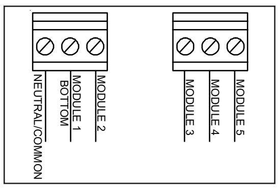
Figure 1. Wiring Cat. No. 102TBS
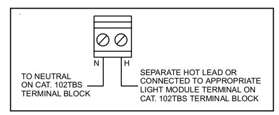
Figure 2. Wiring Cat. No. 102SIG*T with Optional Tone Module
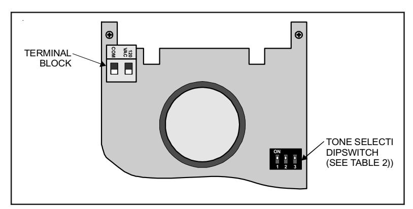
Figure 3. Cat. No. 102SIGMT PC Board (120V version shown)