ETW Installation Instructions for 790-900_790-915- I-CS00165-Rev05
Open the original PDF document
View PDF

ETW – Electric Through Wires
Door and Frame Preparation
For a grout filled frame, install a Mortar Box (HAGER 430). Failure to do so will void the hinge warranty.
- 1. Prepare the door and frame for installation using the standard installation instruction sheet furnished with the hinge, but do not attach the hinge at this time.
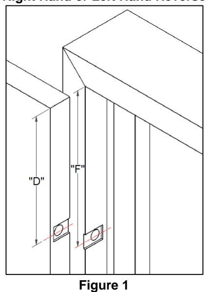
- 2. Using your Stainless-Steel Continuous Hinge model, hinge length and handing; utilize Figure 1, Figure 2 and the tables below to find the correct security plate recess centerline location for your door and frame. Dimensions below are based on Hager's standard ETW centerline locations and the industry standard of 1/8" clearance between the top edge of the door opening and the top edge of the door. Call Hager Technical Support for Modified Length Hinges and Non-Standard ETW centerline location.
790-900
| Hinge Length |
ETW
Security Plate Pair Centerline Location (measured from the top of the hinge) |
Right Hand or Left Hand
Reverse Security Plate Recess Centerline Locations |
Left Hand or Right Hand
Reverse Security Plate Recess Centerline Locations |
||
|---|---|---|---|---|---|
| D | F | D | F | ||
| 79" | 41 1/2 | 42 1/2 | 40 5/8 | 40 1/2 | 42 5/8 |
| 83" | 43 1/2 | 42 1/2 | 44 5/8 | 44 1/2 | 42 5/8 |
| 85" | 45 1/2 | 46 1/2 | 44 5/8 | 44 1/2 | 46 5/8 |
| 95" | 55 3/8 | 54 3/8 | 56 1/2 | 56 3/8 | 54 1/2 |
| 119" | 79 1/8 | 78 1/8 | 80 1/4 | 80 1/8 | 78 1/4 |
790-915
| Hinge Length |
ETW Security Plate Pair
Right Hand or Left Hand |
Left Hand or Right Hand
Reverse Security Plate Recess Centerline Locations |
|||
|---|---|---|---|---|---|
| Centerline Location |
Reverse
Security Plate Recess Centerline Locations |
||||
| (measured from the top of the hinge) | |||||
| D | F | D | F | ||
| 79" | 41 1/2 | 42 1/2 | 40 5/8 | 40 1/2 | 42 5/8 |
| 83" | 43 1/2 | 42 1/2 | 44 5/8 | 44 1/2 | 42 5/8 |
| 85" | 45 1/2 | 46 1/2 | 44 5/8 | 46 1/2 | 44 5/8 |
| 95" | 55 3/8 | 54 3/8 | 56 1/2 | 56 3/8 | 54 1/2 |
| 119" | 79 1/8 | 78 1/8 | 80 1/4 | 80 1/8 | 78 1/4 |
Right Hand or Left Hand Reverse
Left Hand or Right Hand Reverse
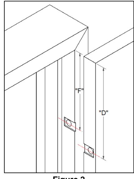
Figure 2

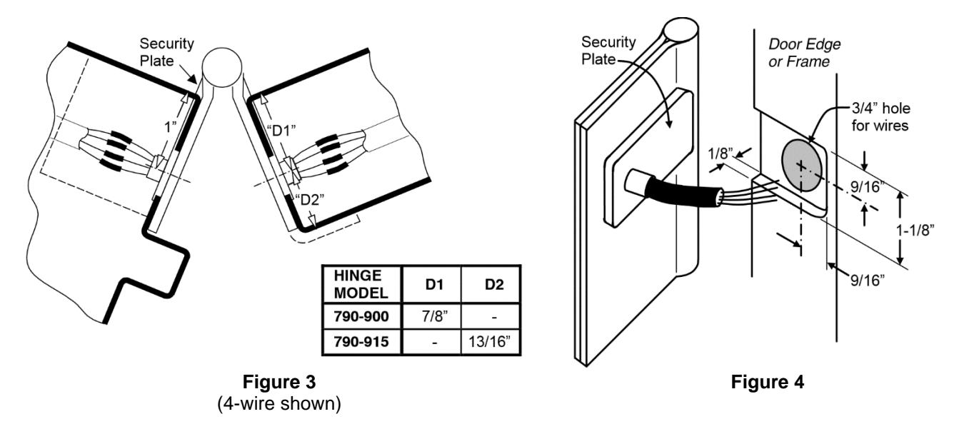
3. Using the recess centerline locations above and in Figure 3, drill a 3/4" diameter access hole in both the frame and the door. Using Figure 4, mortise a 1/8" deep recess for a flush fit of the security plate. After drilling and mortising, deburr the holes to prevent damage to the wire leads.
Installation
- 1. Connect the system wires from the door to the appropriate leads of the hinge door leaf as described in the system wiring diagram found in Figure 5. Insulate the bare end of any unused wires.
- 2. Carefully slide the wires back through the access hole in the door. Make sure they are placed so that they will not be cut or pinched as installation is completed. Attach the hinge to the door per the standard installation instruction sheet supplied with the hinge.
- 3. Position the door at 90 degrees to the frame. Connect the system wires from the frame to the appropriate leads of the hinge frame leaf. Insulate the bare end of any unused wires.
- 4. Carefully slide the wires back through the access hole in the frame. Make sure they are placed so that they will not be cut or pinched as installation is completed.
- 5. Attach the hinge to the frame per the standard installation instruction sheet supplied with the hinge.
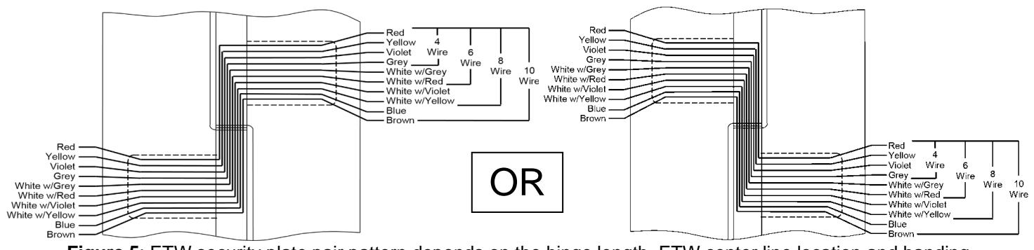
Figure 5 : ETW security plate pair pattern depends on the hinge length, ETW center line location and handing
| MAXIMUM ELECTRICAL | |||||
|---|---|---|---|---|---|
| RATING CONTACT | |||||
| Volts: | 30VAC/DC | ||||
| Amperes: | 3.5A | ||||