ETM 5 Installation Instruction
Open the original PDF document
View PDFInstallation Instructions for all ETH/ETM Models

Applications:
The ETH and ETM hinges are used to pass low voltage power and/or signalling from a door frame to the door in order to power locksets, exit devices and door monitoring devices such as door position switches, request-to-exit switches, etc. ETM (Energy Transfer Monitor) hinges additionally provide a door position sensor in the hinge itself. The quantity and required gauge of wire depends on the hardware being used and the general purpose of the application.
Door Preparation:
The wire chase should be drilled with a 3/8" drill bit at the point noted on the hinge template. The ETH/ETM hinge should always be positioned as one of the center hinges on the door, since the modified hinge no longer meets manufacturers load bearing specifications. A starter hole of 3/4" Diameter x 1- 1/2" deep is recommended for positioning the hinge wire (see note #1).
Frame Preparation:
Mark and drill hole to receive the wires from the ETH hinge (see note #1).
Warnings:
- 1. Be careful not to pinch wires when securing the hinge.
- 2. Do not allow the hinge to dangle by the wire during installation.
Notes:
- 1. In fire rated conditions be sure to confirm the maximum starter hole diameter and depth with the appropriate testing agency.
- 2. Steel based hinges are for interior use only. Use stainless steel or brass based hinges for exterior installations
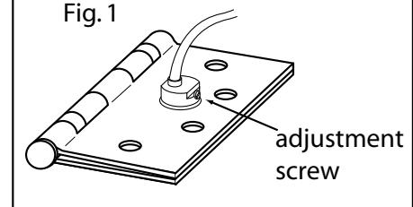
Monitor Adjustment and Specifications (if applicable):
Clockwise wider gap, Counterclockwise narrow gap. (Fig. 1)
Hinge is adjusted with a 1/4" gap from factory which equates to the door opening 1-1/2" for a 3' door and 2" for a 4' door before triggering the monitor switch.
Note: Monitor Wire Template is the same as standard template on pg. 2
ETM Wiring Code:
Mechanical Switch Magnetic Switch
Yellow/Black · Common (C) White: Blue:
Blue/White: Normally Open (NO) Red/White: Black: Normally Closed (NC)
Switch Ratings:
50-100 mA. 30VDC Electrical: In-rush Current: NC & NO: 0.5 A max
Electrical Specifications (Maximum Continuous rating):
| Command Access Monitor Model | ||||||||||||
|---|---|---|---|---|---|---|---|---|---|---|---|---|
| Command Access Model | Zin | Mills | 10 | ETM | - | - | - | - | ||||
| ETH2W | 2 | 20 | 4.0 | 16.0 | ETM2W | 2 | 20 | 4.0 | 16.0 | |||
| ETH4W - ETH6W | 4-6 | 26 | 1.0 | N/A | ETM4W - ETM6W | 4-6 | 26 | 1.0 | N/A | |||
| ETH8W - ETH12W | 8-12 | 28 | 1.0 | N/A | ETM8W - ETM12W | 8-12 | 28 | 1.0 | N/A | |||
| ETH2WH | 2 | 18 | 5.0 | 16.0 | ETM2WH | 2 | 18 | 5.0 | 16.0 | |||
| ETH4WH - ETH6WH | 1MU ETH6MH 2 | 18 | 5.0 | 16.0 | ETM4WH - ETM6WH | 2 | 18 | 5.0 | 16.0 | |||
| 2-4 | 26 | 1.0 | N/A | ETIVIAVVII - ETIVIOVVII | 2-4 | 26 | 1.0 | N/A | ||||
| ETH8WH - ETH12WH | 2 | 20 | 4.0 | 16.0 | ETM8WH | 2 | 20 | 4.0 | 16.0 | |||
| 6-10 | 6-10 28 1.0 N/A | ETIMOWIT | 28 | 1.0 | N/A | |||||||
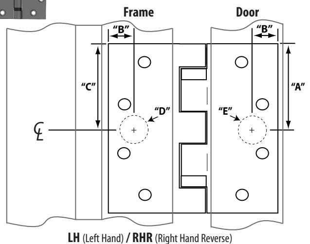
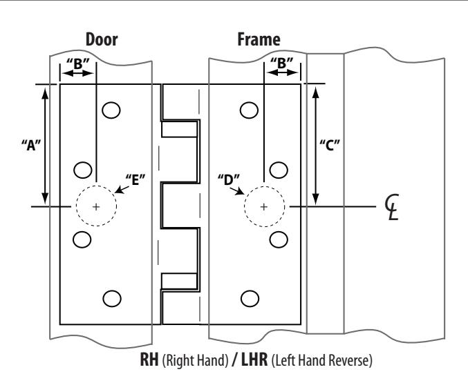
Hinge Template
5 Knuckle Standard Weight
Template: HT579-01
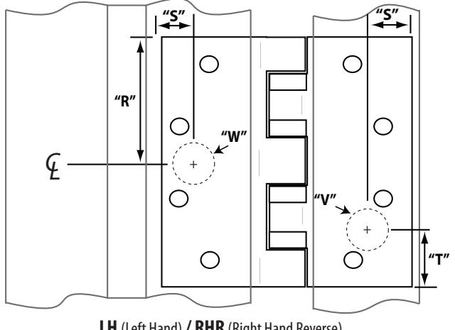
5 Knuckle Heavy Weight
Frame
5 Knuckle Swing Clear Standard/Heavy Weight
Door
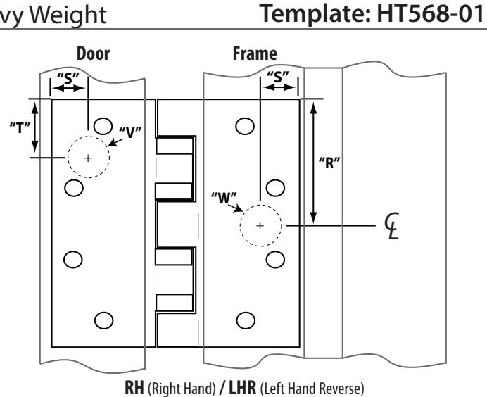
LH (Left Hand) / RHR (Right Hand Reverse)
5 Knuckle Standard Weight
| 5 Knuckle Heavy Weight | |
|---|---|
| Hinge Size | All 5 Knuckle SwingClears |
| Α | В | C | Е | D | R | S | Т | V | W | |
|---|---|---|---|---|---|---|---|---|---|---|
| 2" | 5/8" | 2" | 3/4" | 7/8" | 4" x 4" | - | - | - | - 1 | - |
| 2-1/4" | 5/8" | 2-1/4" | 3/4" | 7/8" | 4-1/2" x 4" | 2-1/4" | 5/8" | 1-1/16" | 3/4" | 7/8" |
| 2-1/4" | 5/8" | 2-1/4" | 3/4" | 7/8" | 4-1/2" x 4-1/2" | 2-1/4" | 5/8" | 1-1/16" | 3/4" | 7/8" |
| 2-1/4" | 5/8" | 2-1/4" | 3/4" | 7/8" | 4-1/2" x 5" | 2-1/4" | 5/8" | 1-1/16" | 3/4" | 7/8" |
| 2-1/4" | 5/8" | 2-1/4" | 3/4" | 7/8" | 4-1/2" x 6" | 2-1/4" | 5/8" | 1-1/16" | 3/4" | 7/8" |
| 2-1/2" | 5/8" | 2-1/2" | 3/4" | 7/8" | 5" x 4" | 2-1/2" | 5/8" | 1-1/8" | 3/4" | 7/8" |
| 2-1/2" | 5/8" | 2-1/2" | 3/4" | 7/8" | 5" x 4-1/2" | 2-1/2" | 5/8" | 1-1/8" | 3/4" | 7/8" |
| 2-1/2" | 5/8" | 2-1/2" | 3/4" | 7/8" | 5" x 5" | 2-1/2" | 5/8" | 1-1/8" | 3/4" | 7/8" |
| 2-1/2" | 5/8" | 2-1/2" | 3/4" | 7/8" | 5" x 6" | 2-1/2" | 5/8" | 1-1/8" | 3/4" | 7/8" |