ETM 4,6,8, and10 Installation Instructions – Screwdriver Adjustment Version I-CT00072
Open the original PDF document
View PDF

INSTALLATION INSTRUCTIONS HAGER ETM4, ETM6, ETM8 & ETM10 HINGES
APPLICATION PROCEDURE
- For use with ETM4, ETM6, ETM8 & ETM10 concealed electric through wire/monitored hinges.
- Steel hinges for interior use only.
- Brass and stainless steel hinges for interior and exterior use.
- Install with Hager 430 mortar box on mortar filled frames. Failure to install mortar box will void manufacturer's warranty.
ELECTRICAL RATINGS
Monitor Switch
- Maximum electrical rating of switch: 30 Volts DC @ .5 Amp
- Wire gauge size: 28 AWG
- Closed loop secure
Use black and white wires
When the door is secure (closed position), the monitor switch shows a contact closed state. When the door opens (unsecure position), an open contact is detected as an alarm.
Open loop secure
Use black and green wires
When the door is secure (closed position), the monitor switch contacts are open. When the door opens (unsecure position), a closed contact is detected as an alarm.
THROUGH WIRES
- Each wire rated 50 Volts AC/DC at 3.5 Amps (max.) continuous, or 16 Amps (max.) pulse.
- Maximum pulse width: 400 msec.
- Minimum "off" time between pulses: 10 Seconds
- Wire gauge size: 28 AWG (typical for all models shown).

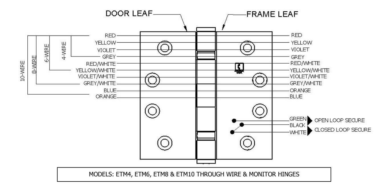
WIRE GAUGE SIZE: 28 AWG (TYPICAL FOR ALL MODELS SHOWN)
- For current ratings larger than 1 Amp, use two or more wires in parallel. Make sure same colored wires are connected properly on both sides of hinge.
- Maximum total current for a four wire hinge is two times the maximum current shown in the electrical ratings chart: two wires current in, two wires current out of door.
- Maximum total current for an eight wire hinge is four times the maximum current shown in the electrical ratings chart: four wires current in, four wires current out of door.
DOOR AND FRAME PREPARATION
- Door and frame must be prepared in accordance with the appropriate through wire & monitored hinge template.
- Through wire & monitored hinges are non-load bearing and must be mounted in the center hinge position only.
- Do not attempt to disassemble hinge. Hinge must be installed assembled. If hinge is disassembled, manufacturer's warranty will be void.
- Wire access holes must be free of burrs and sharp corners. Check to make sure that hinge fits freely in prep. To avoid damaging and or shortened life, do not force hinge into prep holes.
- Rev 1 Rev Date: 8/2012 Page 2 of 3 Hang the door on the top and bottom hinges first. (Note: these are non-electrical hinges)

INSTALLATION
- Attach wires in accordance with project wiring diagrams.
- Open door for access to jamb preps.
- Extract interior wiring through the prep holes from the door and jamb.
-
Terminate wire connections with appropriate crimp splices or wire nuts. Note: it is helpful to stagger terminations. This allows for easy insertion of wires through prep holes.
- Do not hang hinge by wires during installation or serious damage could occur.
- Insulate all ends of unused wires. After all terminations are completed, carefully slide wires through prep hole making sure that wires are placed so they will not be cut or pinched as hinge is installed.
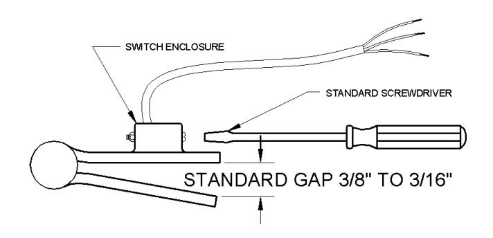
ADJUSTMENT
All concealed electric through wire/monitored hinges are pre-adjusted at the factory. This adjustment is such that the door cannot be opened more than 2" inches before the switch contacts change state. Measurements should be made between the door and the frame opposite the hinge side.
If further adjustments are necessary follow these instructions:
Step 1 : Remove hinge leaf from frame side by removing mounting screws.
Step 2 : Carefully swing hinge from frame prep hole to expose brass switch enclosure. It is not necessary to remove wire connections.
Step 3 : using a small standard blade screwdriver, turn screw clockwise to increase gap. Turn screw one-half turn, then check gap between hinge leaves. Repeat process until desired switch gap is achieved.
If proper gap cannot be achieved within 1-2 full turns, please consult Hager.
Step 4 : Install hinge into frame prep and secure with screws.
Rev 1 Rev Date: 8/2012 Page 3 of 3