ET25 Installation Instruction
Open the original PDF document
View PDFINSTALLATION INSTRUCTIONS
ET25 SERIES


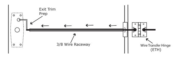
STEP 1 : The door must be machined with a 3/8" wire raceway, Exit Trim & prepped for a energy transfer hinge. Make sure the pocket is free of debris.
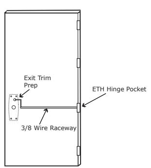
STEP 2 : Run the wires from the ETH hinge through the 3/8" raceway starting at the ETH hinge & exiting into the pocket.
STEP 3 : Screw the ETH hinge to the door. At this time DO NOT connect the hinge wires on the jamb side to the wires coming from the power supply.
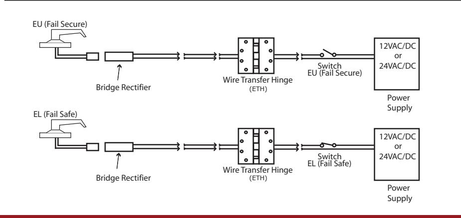
STEP 4 : Connect the wires exiting the pocket to the Bridge Rectifier (included).
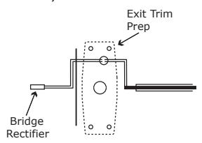
STEP 5 : Connect the Bridge Rectifier to the plug exiting the Electric Exit Trim.
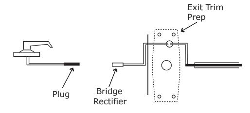
STEP 6 : Carefully slip the connected Electric Exit Trim into the pocket paying close attention not to pinch any wires.
STEP 7: Mount the Electric Exit Trim to door.
STEP 8 : Connect the wires from the power supply at the ETH hinge on the jamb side. Connect the hinge to the jamb.
LEGEND OF TERMS
EU : (Fail Secure) When power is applied, the outside trim will unlock. When power is removed, the outside trim is locked.
EL : (Fail Safe) When power is applied, the outside trim will lock. When power is removed, the outside trim is unlocked.
REE : (Request to Enter Switch) Monitors the outside handle.
ELECTRICAL SPECIFICATIONS
SOLENOIDS:
Operating Voltage 11-30VAC/DC
VOLTSCURRENT24VAC/DC200mA12VAC/DC400mA
SWITCHES: .5A 24VAC/DC
REE: Green - Common (C)
Blue - Normally Open (NO) Gray - Normally Closed (NC)
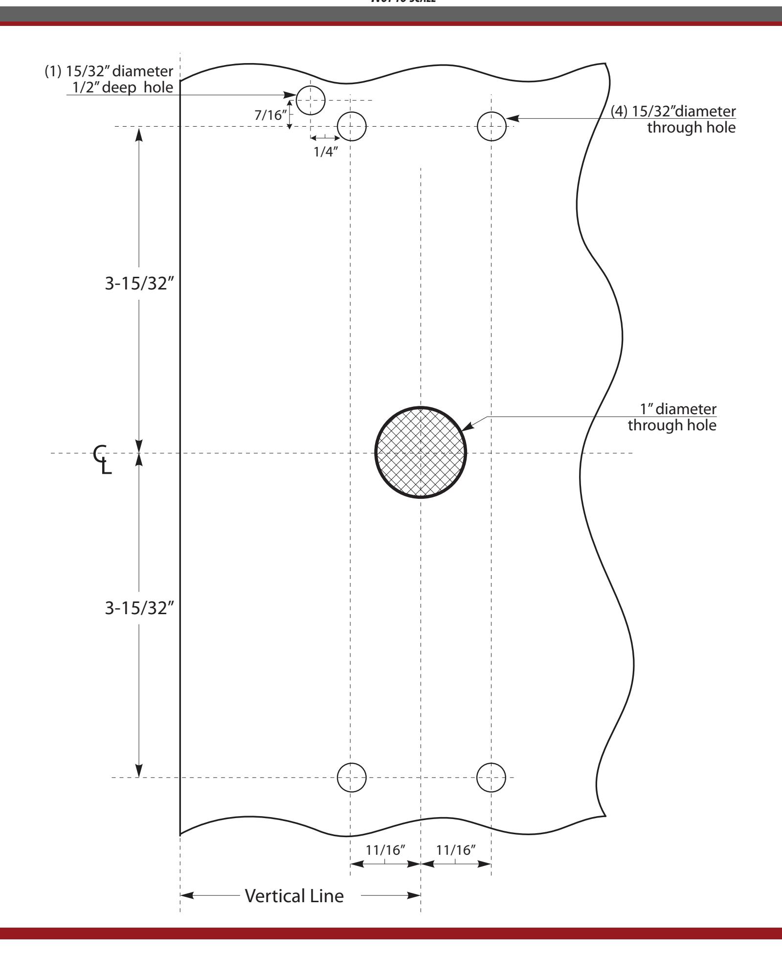
SEE BACK FOR TEMPLATE

*Not to scale TEMPLATE FOR COMMAND ACCESS ET25 RIM/SVR EXIT TRIM
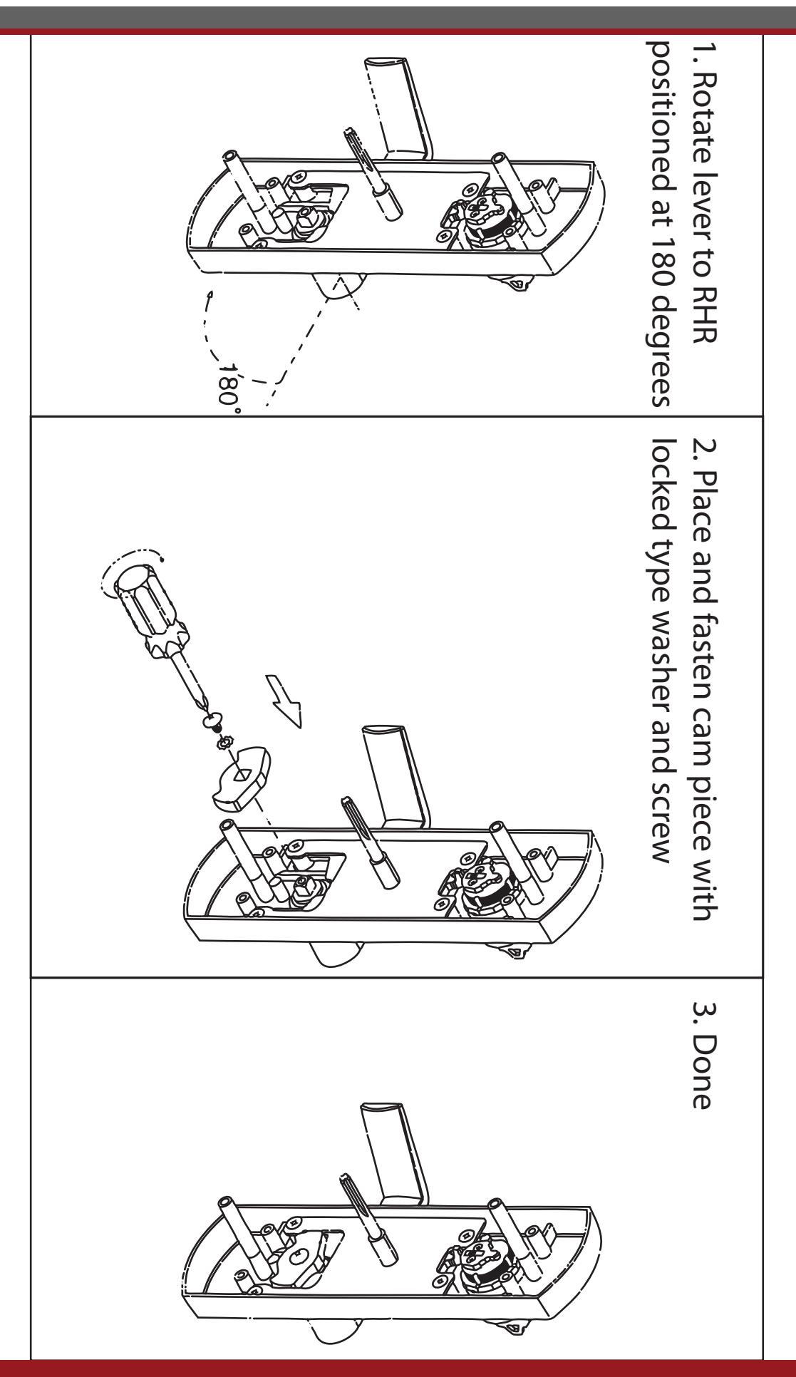
HANDING FOR COMMAND ACCESS ET25 RIM/SVR EXIT TRIM
EU/EL FUNCTION CHANGE FOR COMMAND ACCESS ET25 TRIM

The Command Access ET25 Exit Trim is field selectable between Fail Secure (EU-Electrically Unlocked) and Fail Safe (EL-Electrically Locked).
step 1 :
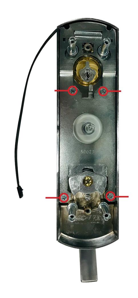
Remove the four screws securing the back plate.
step 2 :
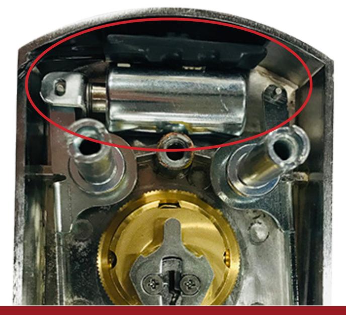
Remove the Solenoid and attached Current Redution Unit from the trim by gently lifting up.
EU/EL FUNCTION CHANGE FOR COMMAND ACCESS ET25 TRIM

step 3 :
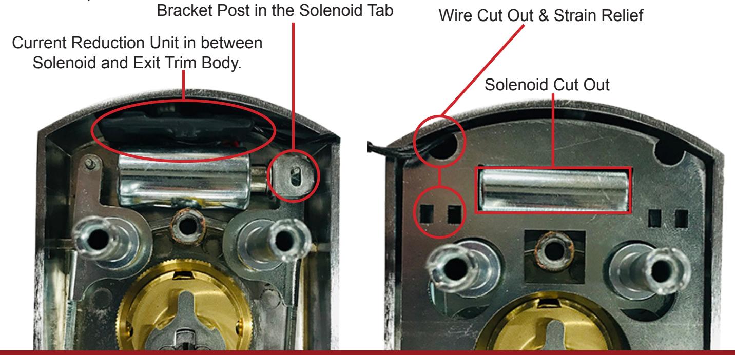
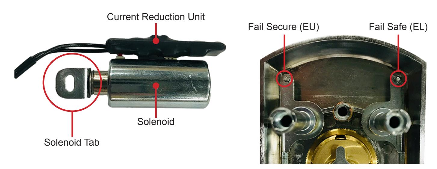
To change the function from EU to EL or visa versa, you will put the Solenoid Tab on the one of the Bracket Posts near the top of the Exit Trim. The left post will be for Fail Secure (EU) and the right post will be for Fail Safe (EL).
step 4 :
Install the Solenoid and its Tab in the desired location, ensuring that the Current Reduction Unit is tucked in between the Solenoid and the Exit Trim body, allowing clearance for the Back Plate to be installed. Install the Back Plate, routing the solenoid wire through the Wire Cutout, tie down wire to Strain Relief using supplied Cable Tie and verify that the solenoid body is resting evenly in its cut out on the back plate.