EPlex 5×70 Installation Instruction Controller
Open the original PDF document
View PDF
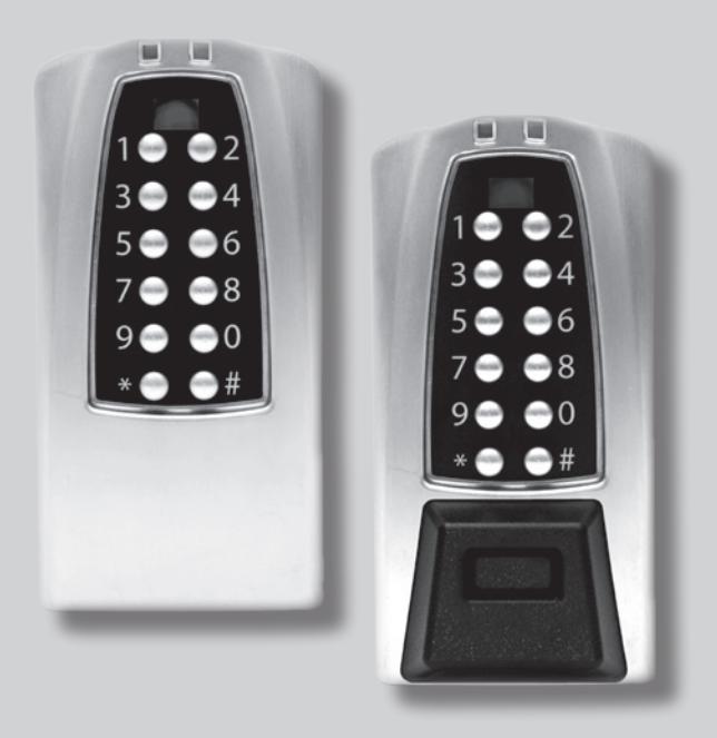

E-PLEX® 5x70 Series Stand-Alone Access Controller
Installation Instructions
Table of Contents
| STEPPAGE | |||||
|---|---|---|---|---|---|
|
Tools Required
|
2 | ||||
| A-1. | Wall Installation4 | ||||
| A-2. | Gang Box Installation5 | ||||
| B. | System Components6 | ||||
| C. | Component Wiring Connections6 | ||||
| D. | Tamper and Security Features11 | ||||
| E. | Software Setting12 | ||||
| F. | Hard Reset Procedure12 | ||||
|
Template
Center of Booklet |
|||||
|
Warranty Card
Center of Booklet |
|||||
WARNING: The Master Code of this unit has been factory preset: 1, 2, 3, 4, 5, 6, 7, 8. To activate lock functions, the master combination must be changed at time of installation.
Warning and Cautions
IMPORTANT: Carefully inspect windows, doorframes, door, lights, etc. to ensure that the recommended procedures will not cause any damage. Kaba Access Control's warranty does not cover damages caused by installation.
CAUTION: Wear safety glasses during installation.
TOOLS REQUIRED
- • Electric Drill/Screwdriver with Variable Speed and Torque
- • Various Flat and Phillips Bits for Power Driver
- • Wire Cutter/Stripper
- • Small Straight (Flat Head) Manual Screwdriver
- • Wall Anchors with #10 and or #6 Flat Head Screws or Masonry Screws
- • Masonry or Wood Drill Bits for Various Surfaces

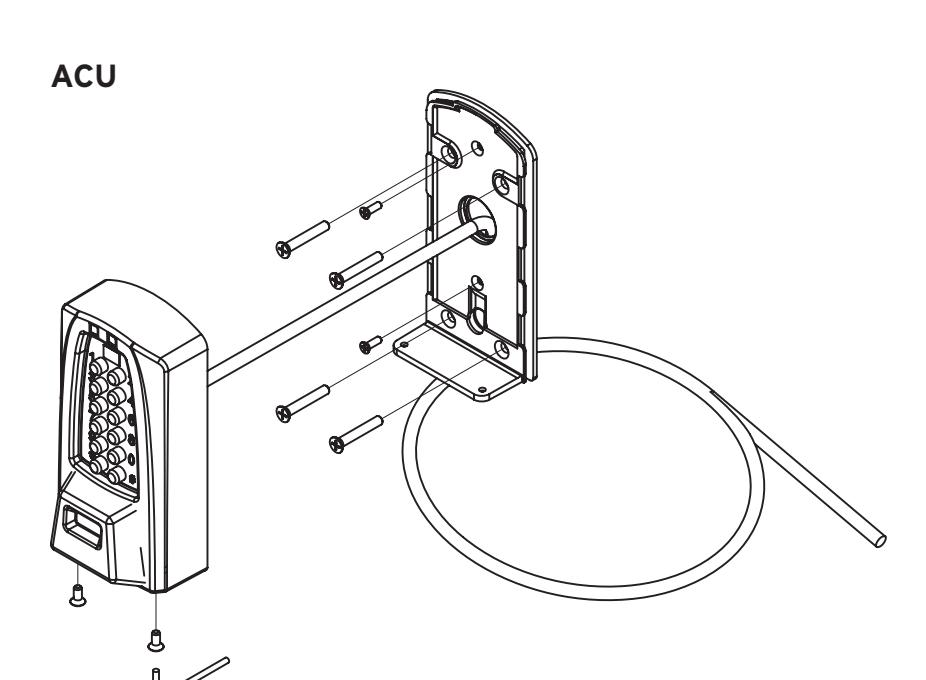
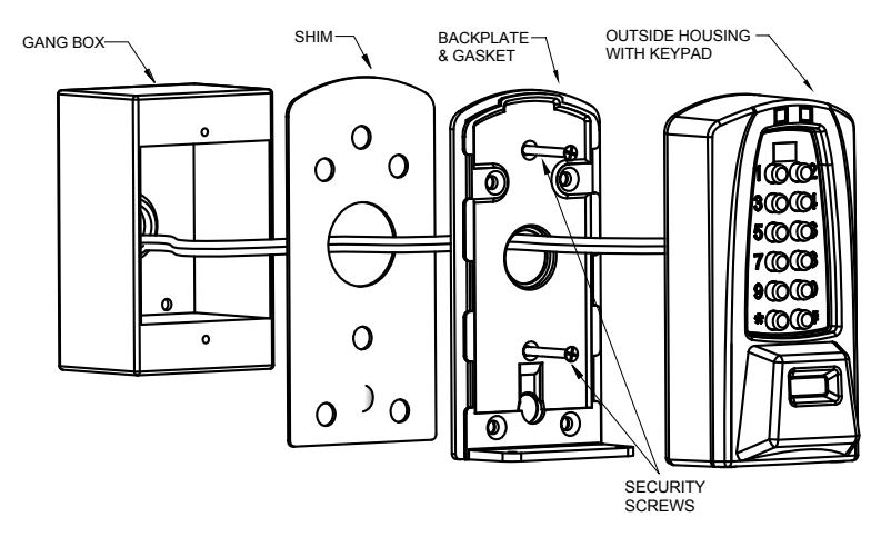
A-1. WALL INSTALLATION
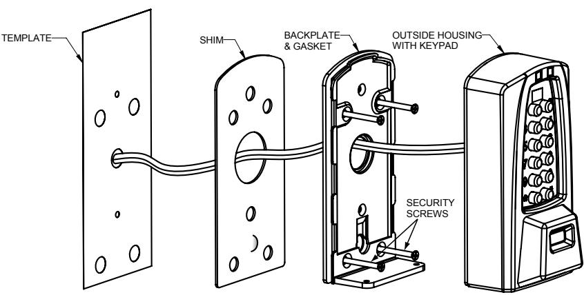
- A-1.1 Please place the template (located in the middle of this manual) on mounting surface to ensure that there are no obstructions; this allows the keypad housing to be moved up, then in and down onto the base plate. Mark and drill four holes for wood screws, wall anchors, or masonry screws and a 1/2" diameter cable hole. Remove the template.
- A-1.2 Thread the cable from the back of the Outside Housing, through the large hole in the Shim and into the hole in the wall. Remove the two security screws from the bottom of the Backplate & Gasket using the small wrench provided in the bag. Slide the back down about one inch while pulling it away from the housing.
- A-1.3 Position Shim, Gasket & Backplate and fasten with #10 Flat Head screws in the four large holes or with two #6 Flat Head screws in the two smaller holes or any combination of each. A minimum of two #6 screws is recommended.
- A-1.4 Push all excess cable into the wall. Hold the top of the Outside Housing about one inch above the top of the Baseplate that is now screwed to the wall and push until the Gasket is flush with the back edges of the Outside Housing. Now push in and down until the bottom of the Baseplate and the bottom of the Outside Housing are flush. Use the wrench provided to replace the security screws.
A-2. GANG BOX INSTALLATION
- A-2.1 Mount Gang Box on the wall referring to the Template to insure clearance above the box. This allows the Keypad Housing to be moved up, then in and down onto the Baseplate. Mark and drill holes for wood screws, wall anchors, or masonry screws and a 1 ⁄2" diameter cable hole.
- A-2.2 Thread the cable from the back of the Outside Housing through the large hole in the Shim, into the hole in the Gang Box and into the wall. Remove the two security screws from the bottom of the Backplate & Gasket using the small wrench provided in the bag. Slide the back down about one inch while pushing it away from the housing.
- A-2.3 Position the Backplate & Gasket, sandwiching the Shim against the Gang Box and fasten the Backplate & Gasket with #6 Flat Head screws into the two smaller holes that line up with the holes in the Gang Box.
- A-2.4 Push all excess cable into the wall conduit. Hold the top of the Outside Housing about one inch above the top of the Baseplate that is now screwed to the Gang Box and push until the Gasket is flush with the back edges of the Outside Housing. Now push in and down until the bottom of the Baseplate and the bottom of the Outside Housing are flush. Use the wrench provided to replace the security screws.
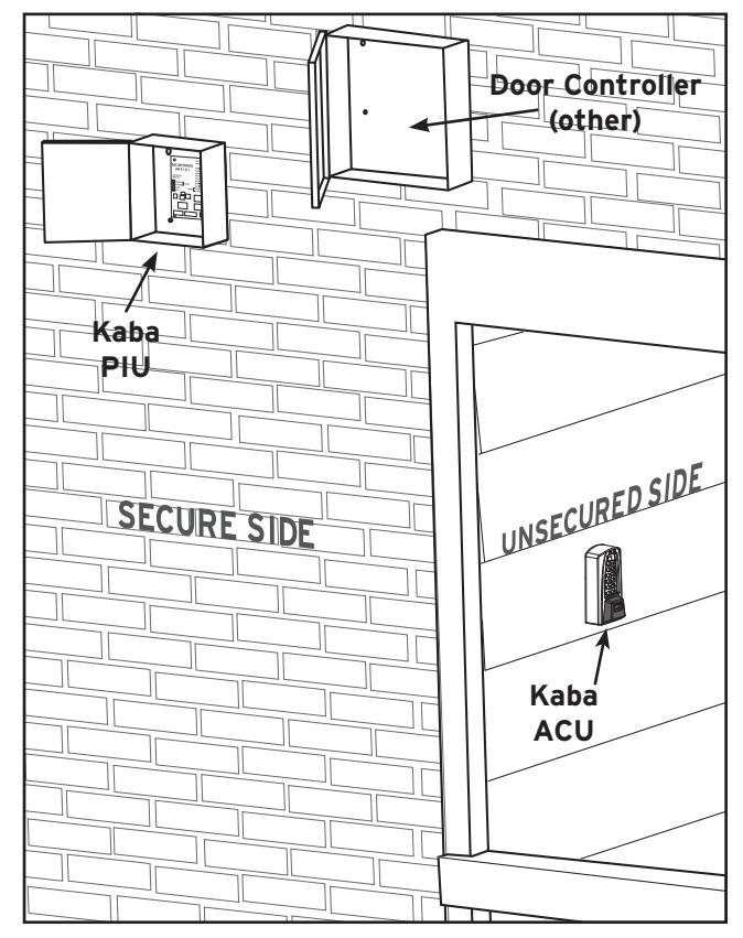
B. SYSTEM COMPONENTS
B-1 Kaba's E-Plex Stand-Alone Access Controller consists of the Access Control Unit (ACU) and the Power Interface Unit (PIU). It is typically used in conjunction with an off-the shelf door controller or power extender (not included) connected to either a magnetic lock or electric strike for securing doors or a parking gate for access control of parking areas. The door controller which must have battery back-up (manufactured by Securitron, Altronix, and others) is typically mounted on the inside wall next to the door or up in a drop ceiling for control of the door through interface with the magnetic lock or electric strike.
C. COMPONENT WIRING CONNECTIONS
6 C-1 Installation of this system is really quite simple. The door controller is interfaced to the device that permits access to the door which typically provides support for either a magnetic lock or electric strike, along with inputs for remote exit (RE) and Fire alarm access.
KABA E-PLEX® LIMITED WARRANTY
Kaba Access Control warrants this product to be free from defects in material and workmanship under normal use and service for a period of three (3) years. Kaba Access Control will repair or replace, at our discretion, locks found by Kaba Access Control analysis to be defective during this period. Our only liability, whether in tort or in contract, under this warranty is to repair or replace products that are returned to Kaba Access Control within the three (3) year warranty period.
This warranty is in lieu of and not in addition to any other warranty or condition, express or implied, including without limitation merchantability, fitness for purpose or absence of latent defects.
ATTENTION: This warranty does not cover problems arising out of improper installation, neglect or misuse. All warranties implied or written will be null and void if the lock is not installed properly and/or if any supplied component part is substituted with a foreign part. If the lock is used with a wall bumper, the warranty is null and void. If a doorstop is required, we recommend the use of a floor secured stop.
The environment and conditions of use determine the life of finishes on Kaba Access Control products. Finishes on Kaba Access Control products are subject to change due to wear and environmental corrosion. Kaba Access Control cannot be held responsible for the deterioration of finishes.
Authorization to Return Goods
Returned merchandise will not be accepted without prior approval. Approvals and Returned Goods Authorization Numbers (RGA Numbers) are available through our Customer Service department in Winston-Salem, NC (800) 849.8324. The serial number of a lock is required to obtain this RGA Number. The issuance of an RGA does not imply that a credit or replacement will be issued.
The RGA number must be included on the address label when material is returned to the factory. All component parts including latches and strikes (even if not inoperative) must be included in the package with return. All merchandise must be returned prepaid and properly packaged to the address indicated.
|
For
your records |
|---|
| Model No.: |
| Date Purchased: |
| Dealer: |
| Name: |
| Telephone: |
| Notes |

For technical assistance please call 1.800.849.TECH (8324) or 336.725.1331
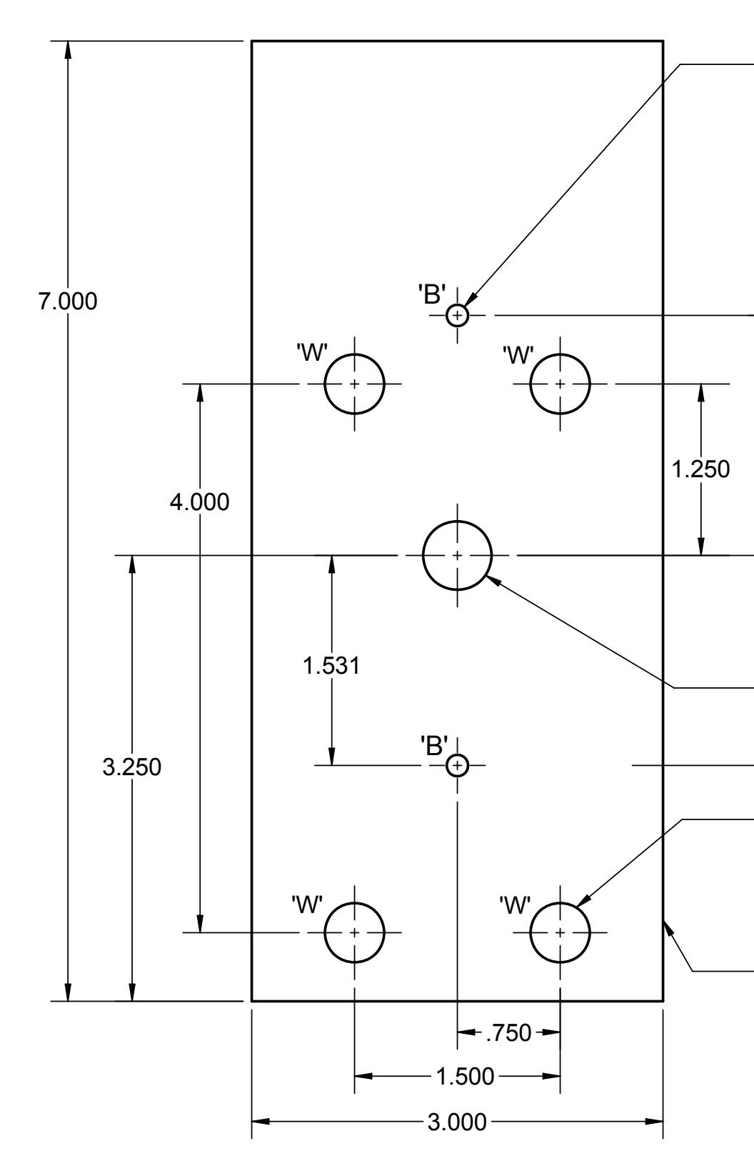
2 HOLES 'B', ARE SPACED FOR DUPLEX OUTLETS, WHEN MOUNTING TO A SINGLE GANG OUTLET BOX. ALIGN THE HOLE IN THE BACK OF THE BOX TO THE HOLE IN THE WALL MADE FOR THE CABLE, SCREW THE BACK OF THE BOX TO THE WALL, DRILL A 3/8" HOLE INTO A BLANK OUTLET COVER THEN THREAD THE CABLE THROUGH THE SUPPLIED SHIM PLATE, AND ON THROUGH THE BACK OF THE BOX INTO THE WALL HOLE, USE 2 #6 FLAT HEAD SCREWS TO GO THROUGH THE ACU'S BASE HOLES THEN THROUGH THE BLANK COVER INTO THE SINGLE GANG BOX HOLES. (SCREWS NOT PROVIDED) AFTER THE SAC BASE
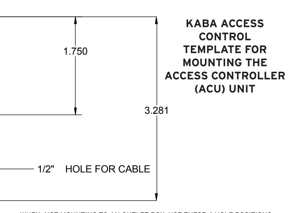
WHEN NOT MOUNTING TO AN OUTLET BOX, USE THESE 4 HOLE POSITIONS, 'W', TO LOCATE DRILL POINTS FOR WALL ANCHORS THAT USE #10 FLAT HEAD SCREWS. FOR MASONRY, 2 DIAGONAL HOLES MAY BE SUFFICIENT. (DO NOT OVERTIGHTEN AND WARP BASE) (WALL ANCHORS ARE NOT PROVIDED.) ALTER-NATIVELY, 4 PILOT HOLES FOR #10 WOOD SCREW FOR CLAPBOARD CONSTRUCTION MAY BE POSITIONED AT THESE LOCATIONS.
THIS RECTANGULAR OUTLINE IS THE APPROXIMATE AREA THAT MUST BE CLEARED AROUND THE ACU.
NO POSTAGE NECESSARY IF MAILED IN THE UNITED STATES
CORNE

BUSINESS REPLY MAIL FIRST-CLASS MAIL PERMIT NO. 1563 WINSTON-SALEM, NC
POSTAGE WILL BE PAID BY ADDRESSEE
KABA ACCESS CONTROL 2941 INDIANA AVENUE WINSTON-SALEM, NC 27199-3770
REGISTRATION CARD
Control, or register online at www.kabaaccess.com. please fill out this registration card and return it to Kaba Access investment and to enable us to better serve you in the future, Thank you for purchasing our product. In order to protect your
|
Co
Ch nt ec ro k l lo he re ck if s. y ou w ou ld lik e m or e inf or m at io n on K ab a Ac ce ss |
Mo
de l Nu mb er |
|---|---|
|
W
ho Lo in ck st sm al led ith y ou r l oc k? M ain te na nc e O th er |
of
Pu rc ha se |
|
of
De ale r Pu rc ha se d Fro m |
|
|
W
ha t w as y ou r r ea so n fo r b uy in g th is loc k? |
|
|
T
ra ini ng C las s O th er (p lea se sp ec ify ) |
|
|
Ho
A A w dv no di er th d tis er yo U em u se lea en t rn a bo ut L P oc K re vio ab ks m a us ith Ac U ce se ss C on tr M In ol ain te Pu rn te sh et na / bu nc We tt e on b L oc ks ? |
ZI
P (P os ta l Co de ) Co un try |
|
R
R ep ep lac lac ing ing a a Ke Ka yle ba E ss lec L oc tro k o nic th A er cc th es an s C K on ab tro a l |
|
|
R
R ep ep lac lac ing ing a a co Ka nv ba en M tio ec ha na nic l k ey al ed Pu lo sh ck bu tto n L oc k |
|
|
Th
N is ew loc In k i sta s: lla tio n |
|
|
Co
W ha m t a mo re n D a oo is r, E be in xe g rc se ise cu R re oo d m) wi th th is loc k? (e .g. Fr on t D oo r, |
|
|
O
S ch th er oo (p l / E lea du se ca sp tio ec na ify l ) H os pit al / H ea lth ca re |
se
ro fi l, or ll ou re t t gi hi st s er re o gi nl st in ra e tio at w n w ca w. rd ka a ba nd ac re ce tu ss rn .co it to m K ab a Ac ce ss |
State City
Phone
Name
Date of
Lock
Address Company
Position
Name
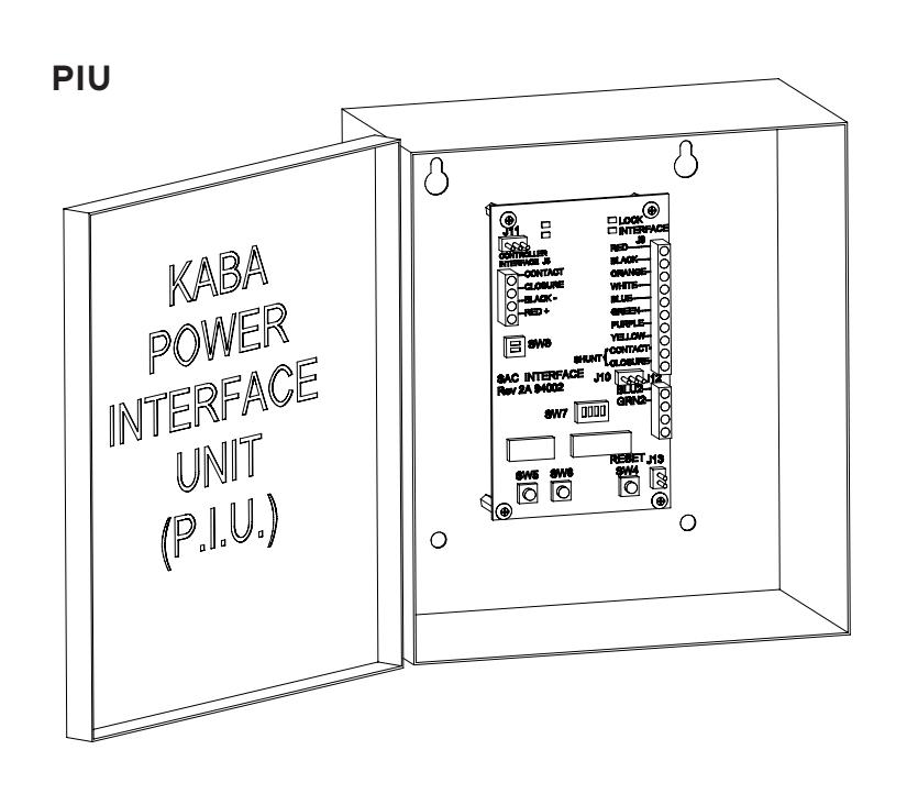
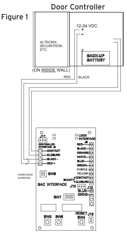
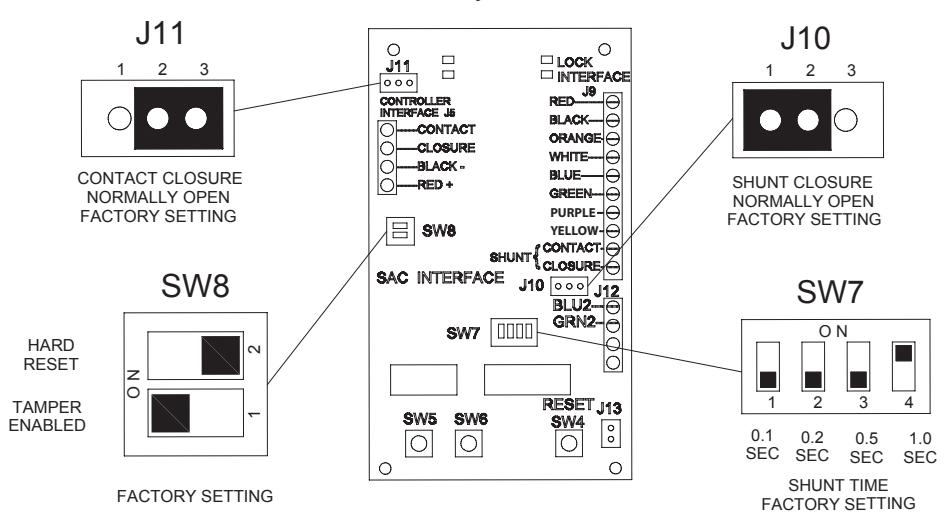
C-2 The PIU requires a four (4) wire interface from the door controller. Two wires provide +12 or +24 VDC to the power interface unit and two wires support normally open (N.O.), or normally closed (N.C.) CONTACT closure from the power interface unit. (See Figure 1 below) The CONTACT closure is factory set to normally open (N.O.), but may be changed to normally closed (N.C.) by moving the jumper on J11 from 2->3 to 1->2. (See Figure 3)
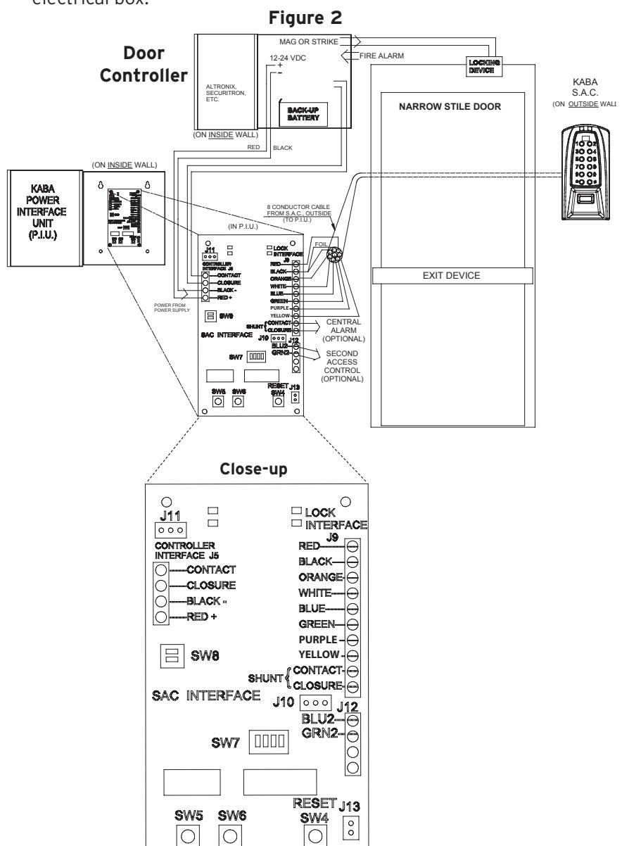
C-3 For applications such as handicapped entrances, vestibules, etc., two ACUs may be used with one PIU. Each ACU requires an eight wire connection using the screw terminals on the interface board assembly inside the PIU enclosure. Each of the two ACU's wires are commoned (connected together at the terminal) except the BLUE and GREEN wires of the second ACU which are connected to J12 and are marked on the PIU. On the opposite end, the eight wires are expanded inside each ACU with the 1.5 feet of cable for ease of installation in most door installations. (See Figure 2)
C-4 Each of the wire colors is labeled on the PIU's interface board assembly next to the connector J9 (See Figure 2). The standard cable length is 1.5 feet. Typical installation will have Kaba's ACU mounted on the unsecured side of the wall next to the door controlled. The door controller, and Kaba's PIU are mounted on the secure side of the door. The ACU is designed to be mounted directly onto different types of wall surfaces or on a single gang electrical box.
D. TAMPER AND SECURITY FEATURES
- D-1 Kaba's Stand-Alone Access Controller has features built in that can provide an extra layer of security to the installation. The Shim Plate installed between the ACU and mounting surface has a bump that extends through a hole in the Backplate. This bump depresses a security switch in the controller to indicate that the installation is secure. If the ACU is opened, vandalized, or removed from the surface it is mounted to, the switch will trigger a disarming of the lock. If tampering is detected by the ACU, the lights at the top of the unit will glow blue until the unit is reset. The ACU must be returned to the secure status by pressing the reset button SW4 on the PIU (See Figure 2) to restore the door access and operation. Since the reset occurs at the PIU, which is on the secure side of the door, another point of access must be available to the secure area. Another method to deal with this is to use a remote reset placed appropriately. A remote reset is afforded by connection to J13. This tamper sensing feature may be disabled by turning off the bottom switch on SW8. (See Figure 3)
- D-2 Another feature of this lock is the SHUNT circuit. SW7 allows selection of one of four switches to control the duration of the Shunt. A SHUNT is typically used to indicate a valid access to a central alarm system. Different alarm systems require different period closures for this purpose and therefore the selections are 0.1, 0.2, 0.5, and 1 second duration. Only ONE switch may be selected. This SHUNT period is also part of the overall period selected for opening. If the SHUNT period is one second, and the period for opening is three seconds, the opening will only last 2 seconds. The door remains secure until the end of the SHUNT period. The SHUNT closure is factory set to normally open (N.O.), but may be changed by moving the jumper on J10 from 1->2 to 2->3. This will make the SHUNT normally closed (N.C.). (See Figure 3)
- D-3 The lock may be tested by using the two switches SW5 & SW6 after installation is complete. Sw5 will open the lock and leave it open until SW6 is pressed, which closes the lock. (See Figure 2)
E. SOFTWARE SETTINGS
- E-1 When configuring the E5070 series SAC using the optional Standard Software, choose the check-box or setting that contains "Entry Lock with Passage (Cylindrical or Mortise without Deadbolt)" during lock setup in the software.
- E-2 When configuring the E5270/5770 series SAC using the mandatory ACS Software, select the "Cylindrical or Mortise without Deadbolt" check-box or setting during lock setup in the software.
F. HARD RESET PROCEDURE
F-1 A hard reset may be necessary if the master code for the lock is lost. A hard reset erases all user codes including the master user and all lock parameters go back to factory default. See the Operations Manual for information on other types of resets that can be performed at the ACU's keypad. This procedure requires two people within hearing range of each other to verify the sequence below. One person must have access to the Lock Interface board assembly inside the PIU enclosure on the secure side and another person must be located at the ACU unit on the non-secure side of the door.
Steps 2, 3, and 4 below must be completed within 5 seconds
- 1. Person 1: Unlock and open cover to PIU unit
- 2. Person 1: Slide the TOP switch of SW8 on the PIU's Lock Interface board to ON (See Figure 3)
- 3. Person 2: Press the # key on the ACU's keypad within 5 seconds
-
4. Person 1: Slide the
TOP
switch of
SW8
on the
PIU's
Lock Interface board to
OFF
and close cover on
PIU
unit
- 5. Person 2: Observe Green and Red LEDs flashing on ACU
- 6. Person 2: Press 1-2-3-4-5-6-7-8 on Keypad, then press #
- 7. The ACU is now in Factory Default Setup
Figure 3
| Notes | |||
|---|---|---|---|


Kaba ADS Americas 2941 Indiana Avenue Winston-Salem, NC 27105 USA Tel: (800) 849.8324 (336) 725.1331 Fax: (800) 346.9640 (336) 725.3269